IR spectrometry cell with temperature control means

a technology of ir spectrometry and sample cell, which is applied in the direction of spectrometry/spectrophotometry/monochromator, optical radiation measurement, instruments, etc., can solve the problems of temperature increase, temperature increase, and heat transfer from heat resistors, through metal heating blocks, to the temperature sensor takes some time, so as to improve the temperature stability of the sample cell

Active Publication Date: 2016-08-16
PERKINELMER U S LLC
View PDF15 Cites 2 Cited by
  • Summary
  • Abstract
  • Description
  • Claims
  • Application Information

AI Technical Summary

Benefits of technology

[0007]It is an object of the invention to improve the temperature stability of the sample cell.SUMMARY OF THE INVENTION
[0009]The use of the heating foil instead of the heating resistors of the prior art gives at least two important advantages. A first advantage is that when the heating foil is attached to the transparent walls of the cavity itself, the source of heat is very close to the liquid to be heated. As a result, the heating of the liquid to be analyzed is much more direct than in the prior art embodiments wherein the metal housing is to be heated first. Because the heating element is closer to the position where the temperature is to be controlled, the heating effect of the liquid is much more direct and temperature fluctuations are reduced.
[0010]A further advantage of using the heat foil is that it can easily be provided in any desired shape. For example, a ring shaped heating foil may be used wherein the ring encircles that part of the transparent plate where the IR light beam is to enter (or leave) the cavity. Instead of only heating the sample cell at one or a few positions, the heating element may be designed to heat a larger surface area. This results in a more evenly distributed heat supply and increased control over the temperature of the liquid to be analyzed. Consequently, according to the invention, not only temporal, but also spatial temperature fluctuations are minimized.
[0012]The heating foil comprises the temperature sensor. This feature has the advantage that the temperature sensor measures temperatures at a position close to the liquid to be analyzed. The temperature measurement thus provides a more accurate indication of the relevant temperature. With the temperature sensor so close to the heating element, the temperature control loop also becomes faster and thus more accurate. As soon as the temperature starts increasing, the temperature sensor will detect this and the heating element may be turned off. As a result the overshoot in the temperature control loop is minimized.
[0013]In addition to the reduced temporal and spatial temperature fluctuations, the invention also improves the reproducibility of the sample temperature. Subsequently analyzed samples therefore have substantially the same temperature or temperature course, which is very important for reliably analyzing multiple samples.

Problems solved by technology

One of the disadvantages of this setup is that the temperature control loop works too slowly.
This leads, for example, to overshoot.
When the temperature sensor measures a too low temperature, the heat resistors heat the heating block and the temperature increases over time.
The transfer of heat from the heat resistors, through the metal heating block, to the temperature sensor does however take some time.
Even when adapting the temperature control loop in order to compensate for this overshoot, it is not possible to keep the sample at the desired temperature.
However, the use of this single heat source in the larger metal block will always lead to fluctuating temperatures.

Method used


Image

  • IR spectrometry cell with temperature control means
  • IR spectrometry cell with temperature control means
  • IR spectrometry cell with temperature control means

Examples


Embodiment Construction

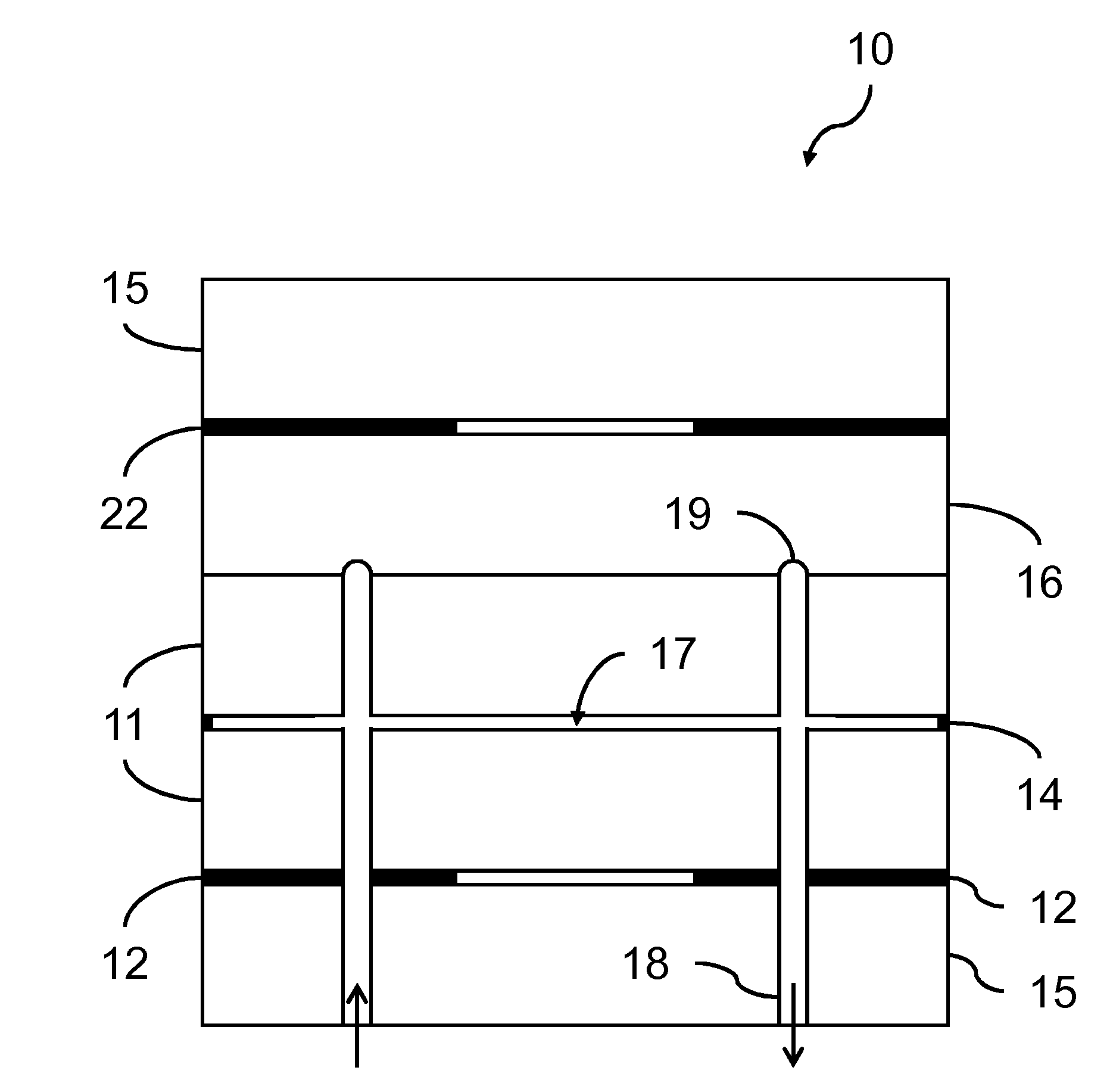
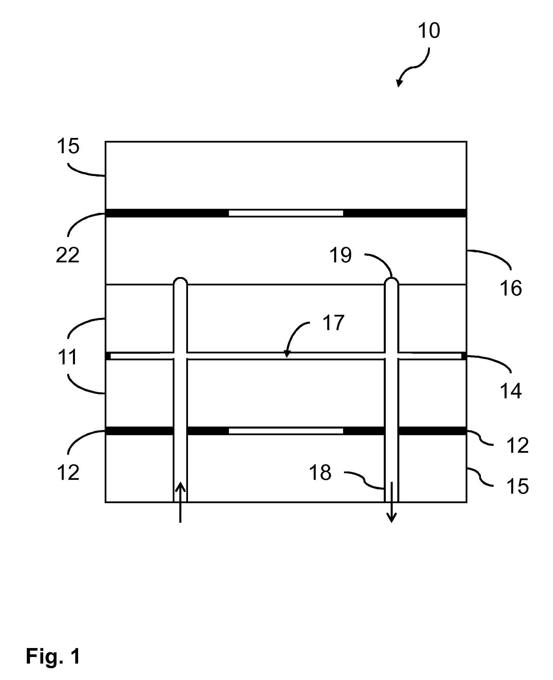
[0020]FIG. 1 schematically shows a cross section of a sample cell 10 according to the invention. The sample cell 10 comprises two transparent plates 11, separated by spacers 14. In, e.g., milk analysis by IR spectrophotometry the spacers usually provide a 20-40 μm (micrometer) wide cavity 17 between the two substantially parallel plates 11. The transparent plates 11 may, e.g., be made of glass, crystalline calcium fluoride (CaF2) or transparent plastics. Also diamond may be used for producing the sample cell 10. In order to be suitable for IR spectrophotometry, the plates 11 only have to be transparent for the IR wavelengths used for the IR spectrophotometry, but it may be practical to select a material that is also transparent for visible light. If the user can look into the cavity 17, it is possible to visually inspect the analyzed liquid. If the sample cell is also used for analysis methods involving light of a different wavelength, the transparent plates 11 also have to be trans...


PUM

PropertyMeasurementUnit
thermally conductiveaaaaaaaaaa
transparentaaaaaaaaaa
temperatureaaaaaaaaaa

Abstract

A sample cell for IR spectrophotometric analysis of a liquid sample is provided. The sample cell comprises two substantially parallel transparent plates enclosing a cavity for holding the liquid sample, and a temperature control loop for controlling a temperature of the liquid sample in the cavity. The temperature control loop comprises at least one temperature sensor for measuring a temperature in or close to the cavity, at least one heating element for increasing a temperature of the liquid sample, and control means, coupled to the temperature sensor and the heating element for controlling the heating element in dependence of the temperature in or close to the cavity. The heating element comprises at least one heating foil which is attached to or thermally coupled to a first one of the transparent plates in such a way to allow an IR light beam to pass through the transparent plates and the cavity without being hindered by the heating foil.

Description

[0001]This application is the U.S. national phase of International Application No. PCT / EP2012 / 065213 filed 3 Aug. 2012 which designated the U.S. and claims priority to EP 11178585.3 filed 24 Aug. 2011, the entire contents of each of which are hereby incorporated by reference.FIELD OF THE INVENTION[0002]This invention relates to a sample cell for IR spectrophotometric analysis of a liquid sample. The sample cell comprises two substantially parallel transparent plates enclosing a cavity for holding the liquid sample and a temperature control loop for controlling a temperature of the liquid sample in the cavity. The temperature control loop comprises at least one temperature sensor for measuring a temperature in or close to the cavity, at least one heating element for increasing a temperature of the liquid sample, and control means, coupled to the temperature sensor and the heating element for controlling the heating element in dependence of the temperature in or close to the cavity.[0...

Claims


Application Information

Patent Timeline
Patent Type & Authority Patents(United States)
IPC IPC(8): G01N21/01G01J3/28G01J3/02G01N21/03G01N21/05G01N21/3577G01N33/04
CPCG01N21/0332G01N21/05G01N21/3577G01J3/0267G01J3/28G01N33/04G01N2021/0346
Inventor TERPSTRA, ANNE GERBEN
Owner PERKINELMER U S LLC
Why Eureka
Try Eureka