Cutting attachment apparatus and method

a technology of attachment apparatus and cutting blade, which is applied in the field of cutting, can solve the problems of slowing down the operation capability of such machines, affecting the operation efficiency of large and heavy machines, and difficulty in performing various cuts to existing concrete structures, etc., and achieves the effects of increasing the insertion depth, and reducing the insertion angl

Active Publication Date: 2016-08-23
JS INNOVATIONS LLC
View PDF10 Cites 9 Cited by
  • Summary
  • Abstract
  • Description
  • Claims
  • Application Information

AI Technical Summary

Benefits of technology

[0010]In one embodiment, the attachment frame includes an A-frame portion, and where the cutting assembly being coupled with the attachment frame includes the cutting assembly being coupled with the attachment frame proximate the A-frame portion, allowing for the cutting assembly to accomplish a cut within a perimeter of the attachment frame.
[0014]In a further embodiment yet, the a cut insertion depth assembly includes a reversible cut depth hydraulic motor for altering the insertion depth of a cut of the cutting assembly, and the manifold including a cut depth hydraulic port set is coupled with the reversible cut depth hydraulic motor. A three position directional valve is included between the host hydraulic port set and the cut depth hydraulic port set, and having first, second and third positions, where actuating the three position valve to the second position drives the reversible cut depth hydraulic motor in a first direction to increases insertion depth of the cut, and actuating the three position valve to the third position drives the reversible cut depth hydraulic motor in a second direction to decreases insertion depth of the cut. In a further embodiment, the cut insertion depth assembly includes a reversible cut angle hydraulic motor for altering the angle of a cut of the cutting assembly, and the manifold includes a cut angle hydraulic port set coupled with the reversible cut angle hydraulic motor. A three position directional valve is coupled between the host hydraulic port set and the cut angle hydraulic port set, and having first, second and third positions, where actuating the three position valve to the second position drives the reversible cut angle hydraulic motor in a first direction to increases an angle of the cut, and actuating the three position valve to the third position drives the reversible cut angle hydraulic motor in a second direction to decreases the cut angle of the cut.

Problems solved by technology

Such machines are heavy and utilize a large, fixed frame design, that in some situations render it difficult to perform various cuts to existing concrete structures, including curbing, driveway aprons, pilings, piers, stanchions, walls, and foundations.
For example, where existing stand alone vehicles are used on uneven surfaces, or surfaces composed of soft materials such as gravel, sand, grass or dirt, such large and heavy machines are often unable to manage the terrain.
Such surfaces slow the operation capabilities of such machines, and impact the precision and accuracy of the cuts made.
However, performing a cut to an existing curb in this manner risks damaging the street during the cut, especially where anything besides a horizontal cut is made.
Further, where the backside of a curb is adjacent another structure, for example, a concrete driveway apron, existing stand alone vehicles have significant risk of damaging the apron while cutting the existing curb.
Further, plunge cuts with stand-alone cutting vehicles are difficult or impossible to accomplish, as are cuts on curbs having a tight turning radius.
Additionally, the stand alone vehicles are limited in their ability to perform cuts at heights above their existing support frame and / or their designed intent.
Yet, should their frame size be increased to increase cutting height capabilities, transport of the larger stand-alone machine would be rendered even more difficult and impractical.
With existing stand alone vehicles, it is difficult or impossible to perform cuts across concrete structures such as concrete walls.
Even if it is possible for these large, stand alone vehicles to perform such cuts, the large stand alone vehicle footprint prevents access to the structure, for example, because of other nearby structures or objects.
In addition, where cutting or other operations are desired on top of an existing structure, for example, a building roof, the size and weight of existing stand-alone cutting vehicles exceed the allowable operating live load capabilities of the structure.
The top of a structure may also have limited available area for a machine to operate.
In such cases, existing stand alone vehicles cannot be employed safely, or cannot be employed at all, to operate on such structures.
Further, where it is desired to make cuts within an existing structure that has limited entry capabilities, for example, a double entry door, the large size of existing stand alone vehicles prevent such cuts to be made.
The size and weight of existing stand alone vehicles makes transport of these machines to job sites difficult, and such transport often encounters difficulties with rural road conditions and Department Of Transportation (DOT) size and weight restrictions.
In addition, where cuts are desired beneath water, existing stand alone vehicles are unable to navigate the terrain adjacent the water, or the water itself, and are thus unable to perform such cuts.

Method used


Image

  • Cutting attachment apparatus and method
  • Cutting attachment apparatus and method
  • Cutting attachment apparatus and method

Examples


Embodiment Construction

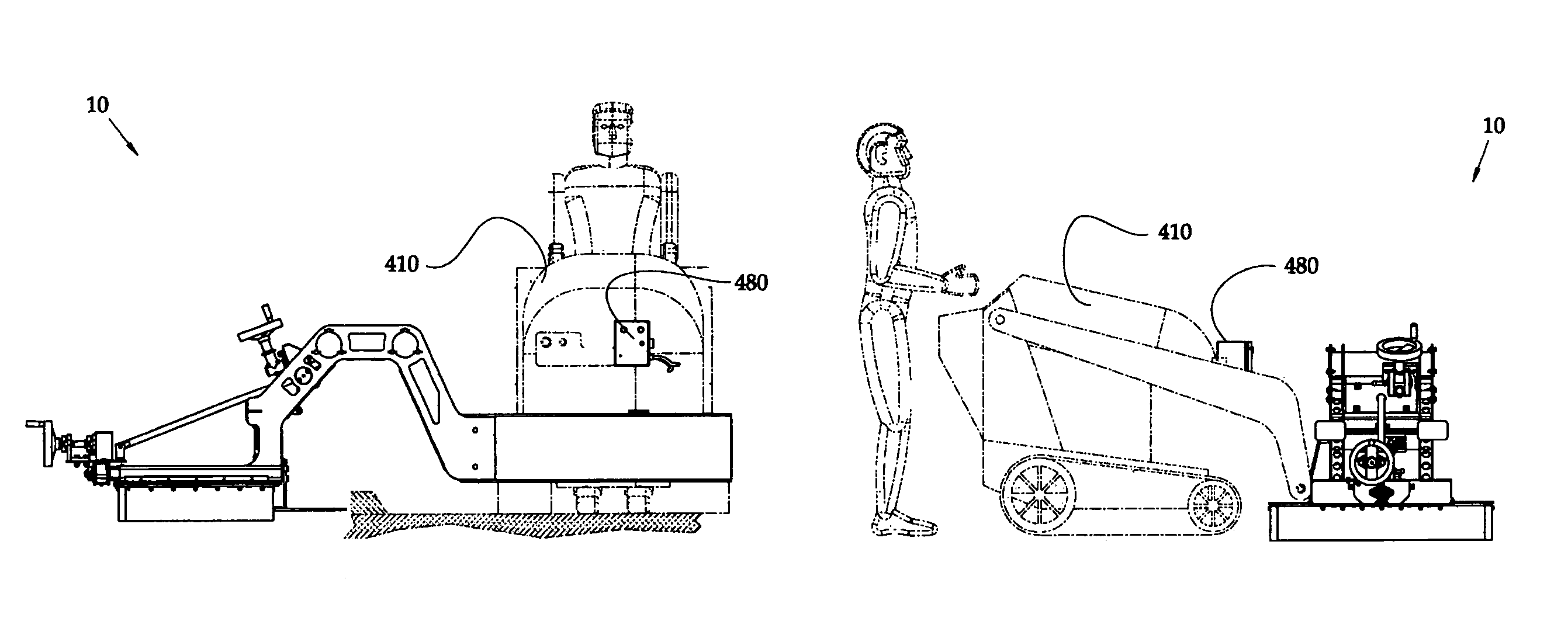
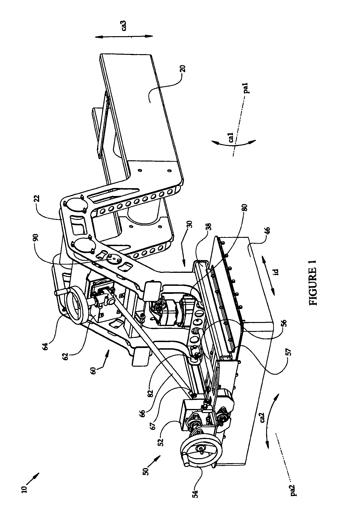
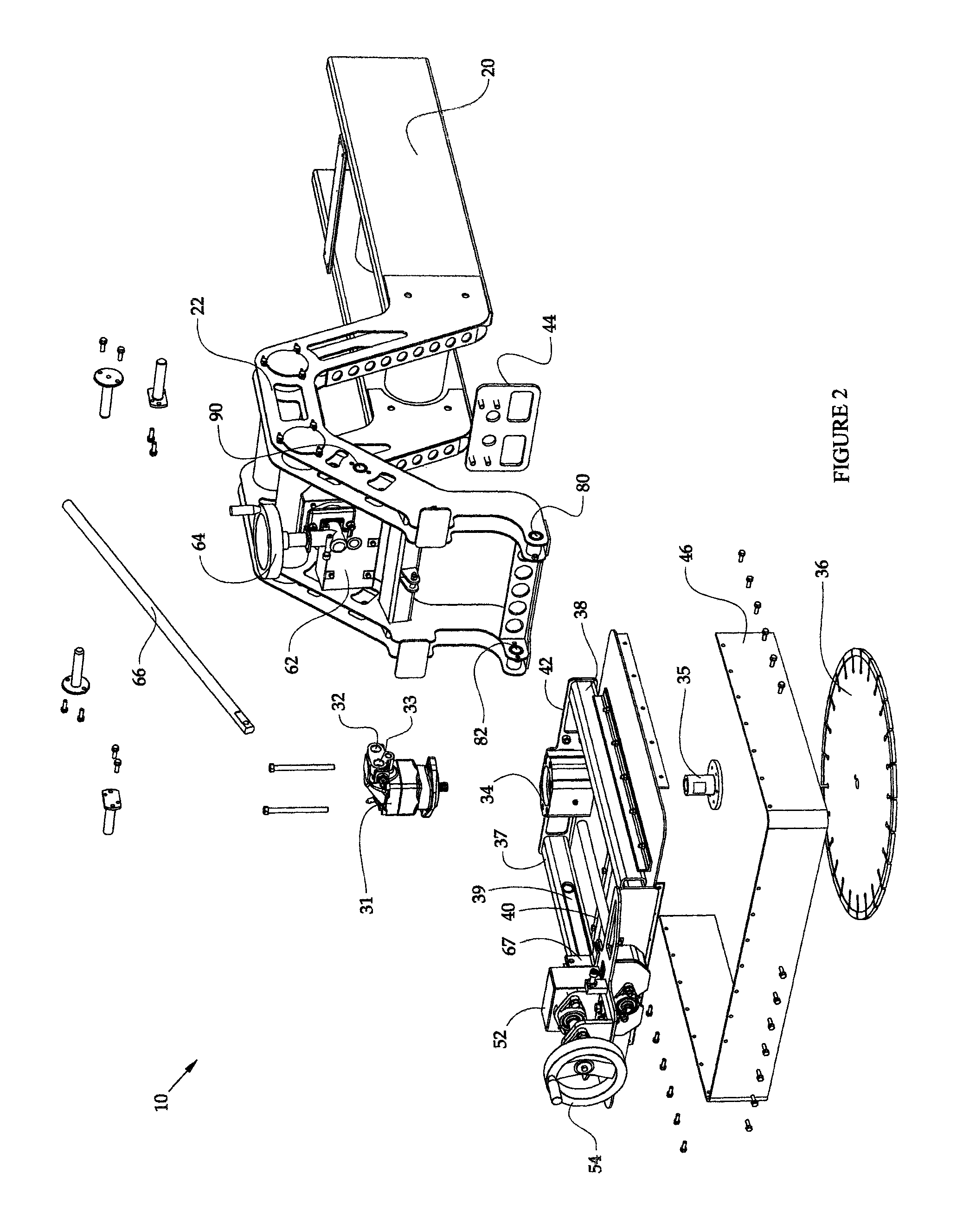
[0044]A cutting attachment apparatus and method comprise an attachment frame, and a host machine interface coupled with the attachment frame for coupling the attachment with a host machine. A cutting assembly is coupled with the attachment frame. A cut insertion depth assembly is coupled with the attachment frame and the cutting assembly for altering the insertion depth of a cut of the cutting assembly, and a cut angle assembly is coupled with the attachment frame and the cutting assembly for altering an angle of the cut of the cutting assembly. In a further embodiment, the attachment frame includes an A-frame portion, and where the cutting assembly being coupled with the attachment frame includes the cutting assembly being coupled with the attachment frame proximate the A-frame portion, allowing for the cutting assembly to accomplish a cut within a perimeter of the attachment frame. In another embodiment, the cutting attachment apparatus extends over the object, where the object ha...


PUM

PropertyMeasurementUnit
90 degree angleaaaaaaaaaa
heightaaaaaaaaaa
heightsaaaaaaaaaa

Abstract

A cutting attachment apparatus and method comprise an attachment frame, and a host machine interface coupled with the attachment frame for coupling the attachment with a host machine. A cutting assembly is coupled with the attachment frame. A cut insertion depth assembly is coupled with the attachment frame and the cutting assembly for altering the insertion depth of a cut of the cutting assembly, and a cut angle assembly is coupled with the attachment frame and the cutting assembly for altering an angle of the cut of the cutting assembly.

Description

TECHNICAL FIELD[0001]This disclosure is directed to cutting, and more particularly, to an attachment for performing cuts to objects and materials.BACKGROUND ART[0002]There are stand alone vehicles that are used to perform cuts to materials and objects, for example, concrete, concrete curbs and concrete driveway aprons. Such machines are heavy and utilize a large, fixed frame design, that in some situations render it difficult to perform various cuts to existing concrete structures, including curbing, driveway aprons, pilings, piers, stanchions, walls, and foundations. For example, where existing stand alone vehicles are used on uneven surfaces, or surfaces composed of soft materials such as gravel, sand, grass or dirt, such large and heavy machines are often unable to manage the terrain. Such surfaces slow the operation capabilities of such machines, and impact the precision and accuracy of the cuts made. Often, a second cutting pass is required to clean up the imprecision and inacc...

Claims


Application Information

Patent Timeline
Patent Type & Authority Patents(United States)
IPC IPC(8): E01C23/09B23D45/02B28D1/04
CPCE01C23/094E01C23/09B28D1/045B23D45/024
Inventor BAASKE, JOHN A.DEMING, STACY L.PENTECOST, MARC W.
Owner JS INNOVATIONS LLC
Why Eureka
Try Eureka