
Magnetically suspended vibration isolator with zero stiffness whose angle degree of freedom is decoupled with a joint ball bearing

a technology of zero stiffness and isolator, which is applied in the direction of fluid pressure measurement, machine support, instruments, etc., can solve the problems of limited reduction of horizontal and vertical stiffness, limited precision and performance of precision measuring instruments and manufacturing equipment, and difficult to further reduce its stiffness, etc., to achieve outstanding low frequency vibration isolation performance and low stiffness

Active Publication Date: 2016-08-23
HARBIN INST OF TECH
View PDF26 Cites 4 Cited by
  • Summary
  • Abstract
  • Description
  • Claims
  • Application Information

AI Technical Summary

Benefits of technology

The present invention solves several problems that existing vibration isolators face such as friction, wear, and introduction of additional stiffness. Using a joint ball bearing and a cylindrical air bearing surface, the angle degree of freedom between the mounting plates can be decoupled without adding any stiffness. Additionally, the invention includes a positioning system and an air pressure control system, which ensures high positioning precision and ideal gravity balance for excellent vibration isolation with zero stiffness. This invention provides low-frequency vibration isolation with outstanding performance while solving issues of stiffness and stability.

Problems solved by technology

With quick development of precision measurement and manufacturing, environmental vibration has become a main factor that limits the precision and performance of precision measuring instruments and manufacturing equipments.
However, for a traditional vibration isolator based on an air spring, it's very difficult to further reduce its stiffness, especially horizontal stiffness.
However, there are still following shortcomings: 1) the extent of reduction of horizontal and vertical stiffness is limited by material property and structural stiffness; 2) horizontal and vertical positioning precision of a vibration isolator based on an air spring is too low to meet the requirement of lithography; 3) a large length of “pendulum” is needed to achieve low horizontal stiffness, easily results large height of vibration isolators, chord-membrane-resonance and poor stability.
It's difficult to meet requirements of low stiffness and high positioning precision in a lithography machine with existing vibration isolators based on air springs.
However, there are still following shortcomings: 1) high positioning precision can't be achieved with presented design; 2) in patent EP1803965A2, there is no rotary degree of freedom around horizontal axes between the upper and lower mounting plates, so stiffness and natural frequency in that direction are both high; in patents EP1803970A2 and US20080193061A1, a rubber block is used to provide the rotary degree of freedom around horizontal axes, however, the angle degree of freedom can't be effectively decoupled due to large angular stiffness of the rubber block.
However, problems of precision positioning and decoupling of angle degree of freedom between the upper and lower mounting plates are still not solved.

Method used


Image

  • Magnetically suspended vibration isolator with zero stiffness whose angle degree of freedom is decoupled with a joint ball bearing
  • Magnetically suspended vibration isolator with zero stiffness whose angle degree of freedom is decoupled with a joint ball bearing
  • Magnetically suspended vibration isolator with zero stiffness whose angle degree of freedom is decoupled with a joint ball bearing

Examples


Embodiment Construction

[0027]Preferred embodiments of the present invention will be described in detail with reference to accompanying drawings.

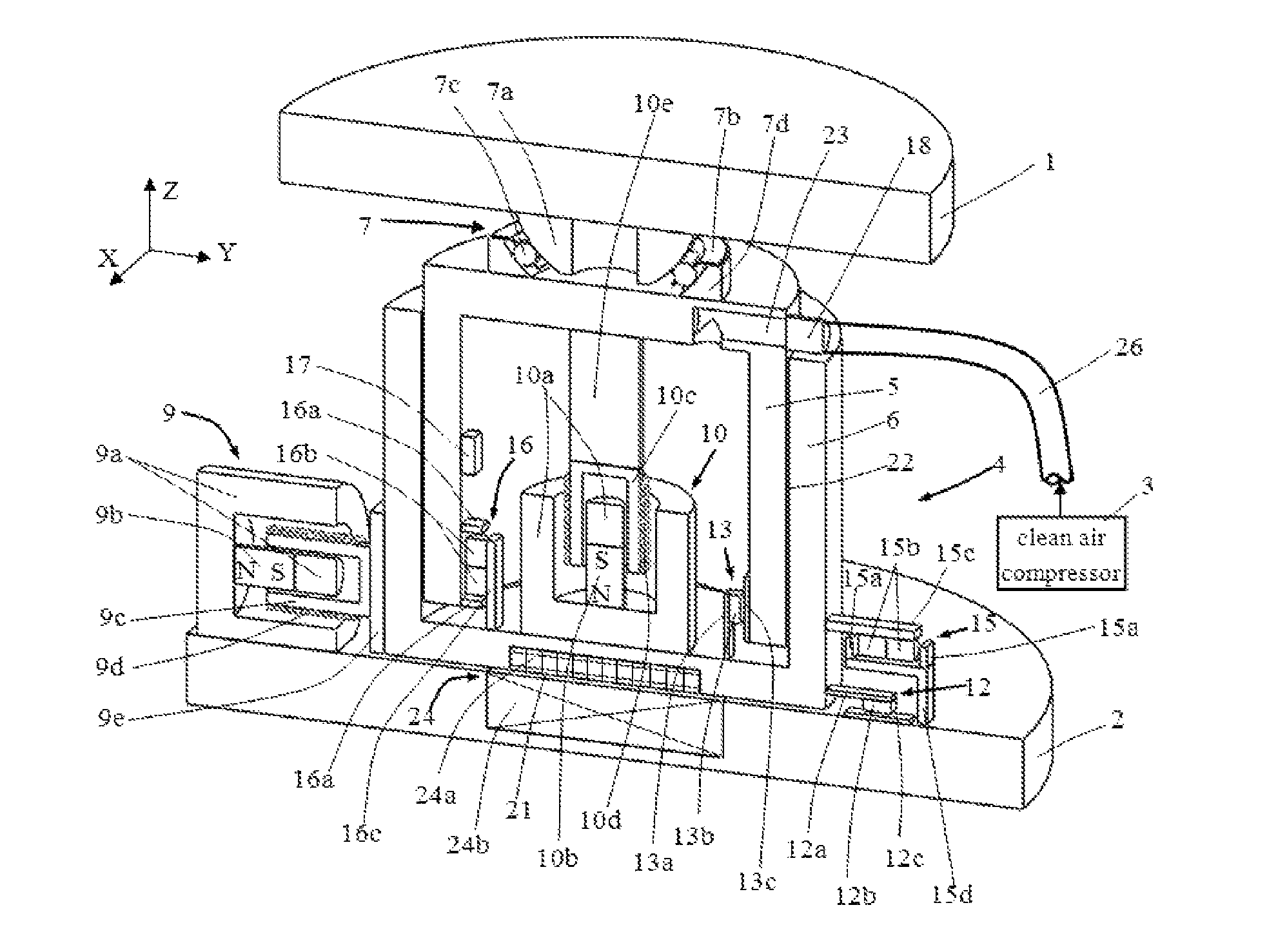
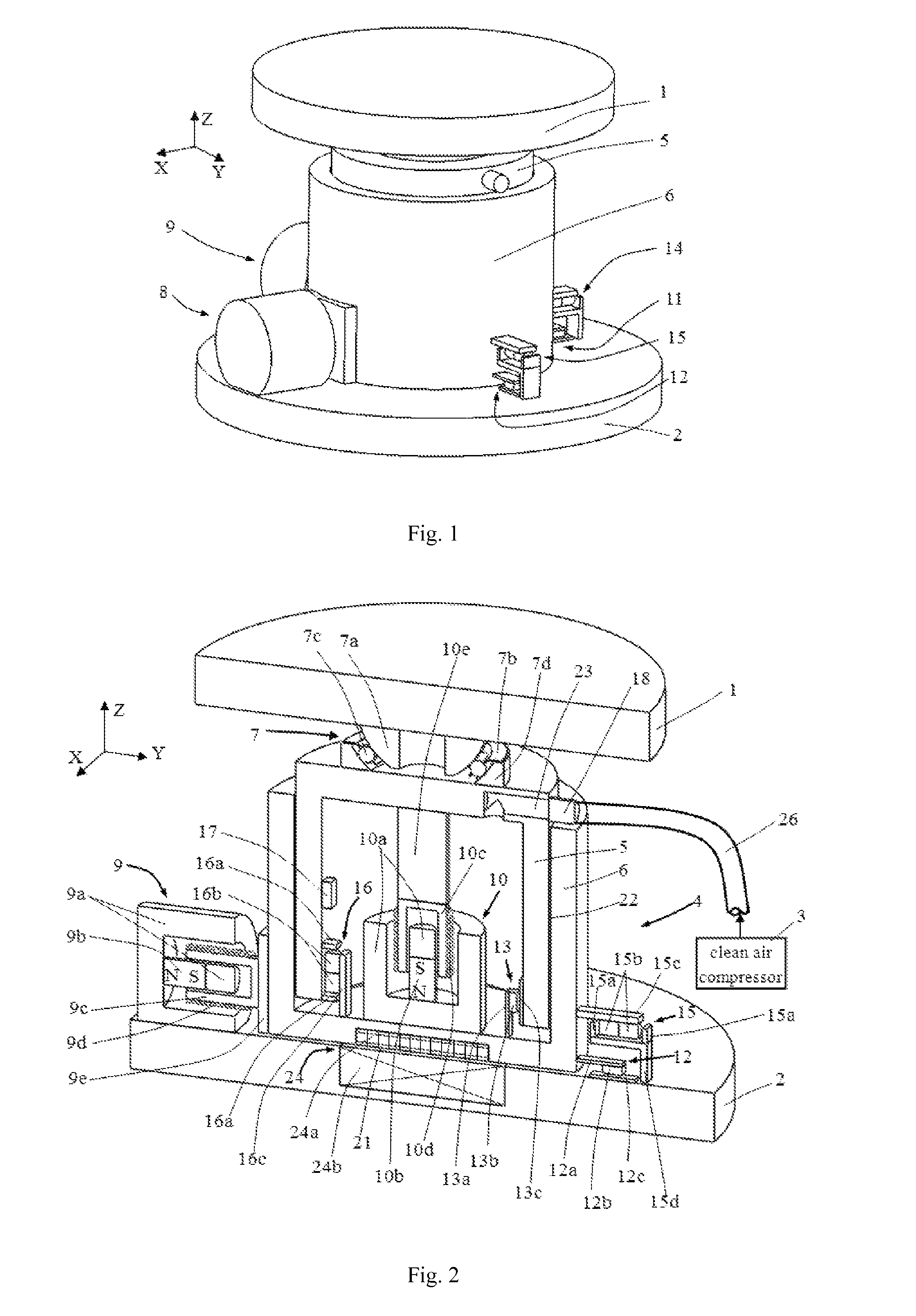
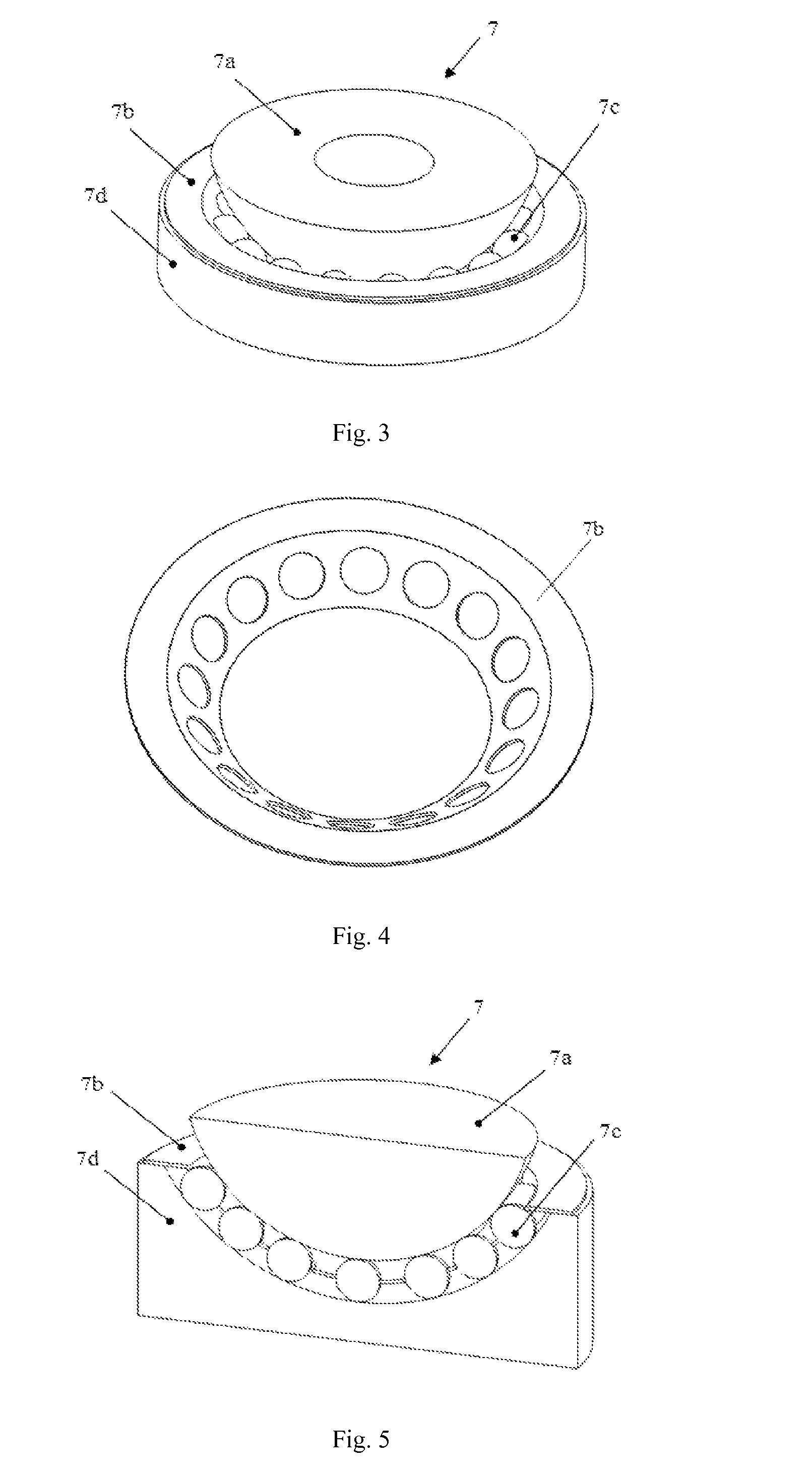
[0028]As shown in FIG. 1, FIG. 2 and FIG. 3, a magnetically suspended vibration isolator with zero stiffness whose angle degree of freedom is decoupled with a joint ball bearing comprises a upper mounting plate 1, a lower mounting plate 2, a clean air compressor 3, an air pipe 26 and a main body 4, the main body 4 is fitted between the upper mounting plate 1 and the lower mounting plate 2, and the clean air compressor 3 is connected to the main body 4 with the air pipe 26; in the main body 4, the lower surface of a downside-down sleeve 6 and the lower mounting plate 2 are lubricated and supported against each other with a magnetically suspended thrust bearing 24, a upside-down piston cylinder 5 is fitted inside the sleeve 6 and they are lubricated against each other with a cylindrical air bearing surface 22, a joint ball bearing 7 is fitted between the piston cyli...


PUM

PropertyMeasurementUnit
thicknessaaaaaaaaaa
frequenciesaaaaaaaaaa
stiffnessaaaaaaaaaa

Abstract

A magnetically suspended vibration isolator with zero stiffness whose angle degree of freedom is decoupled with a joint ball bearing has a main body, in which a sleeve and a lower mounting plate are supported with a magnetically suspended thrust bearing, a piston cylinder and the sleeve are lubricated and supported with a cylinder air bearing surface, and the angle degree of freedom between a upper mounting plate and the lower mounting plate is decoupled with a joint ball bearing; a position close-loop control system comprising voice coil motors, displacement sensors, limit switches, a controller and a driver is introduced, and the relative position between the upper mounting plate and the lower mounting plate is precisely controlled.

Description

CROSS-REFERENCE TO RELATED APPLICATION[0001]This U.S. application claims priority under 35 U.S.C. 371 to, and is a U.S. National Phase app1ication of, the International Patent Application No. PCT / CN2014 / 072279, filed 19 Feb. 2014, which claims the benefit of prior Chinese Application No. 201210574709.3 filed 19 Dec. 2012. The entire contents of the above-mentioned patent applications are incorporated by reference as part of the disclosure of this U.S. application.FIELD OF INVENTION[0002]The present invention relates to a magnetically suspended vibration isolator with zero stiffness whose angle degree of freedom is decoupled with a joint ball bearing, which can be used for low frequency and high performance vibration isolation in precision measurement instruments and manufacturing equipments.DESCRIPTION OF PRIOR ART[0003]With quick development of precision measurement and manufacturing, environmental vibration has become a main factor that limits the precision and performance of prec...

Claims


Application Information

Patent Timeline
Patent Type & Authority Patents(United States)
IPC IPC(8): F16M13/00G01D5/20F16F15/00F16F15/023F16F15/03G01L19/00H02K41/035
CPCF16F15/0232F16F15/03F16F15/002G01D5/20G01L19/0061H02K41/0356F16C32/04F16C32/06
Inventor TAN, JIUBINCUI, JUNNINGWANG, LEI
Owner HARBIN INST OF TECH
Learn More