A problem the construction of the PCT publication solved related to the traditional location of the fluidized bed heat exchange chambers on the outside walls of the lower section of the furnace.
While the CFB boilers grew, it was not possible to increase the size of the fluidized bed heat exchange chambers accordingly, as increasing the height of a heat exchange chamber resulted in the increase of pressure losses in the
fluidization air, and an increase in the width of the
heat exchanger was not possible due to a lack of space.
When all the above-discussed and other considerations were taken into account in the design of the heat exchange arrangement, however, the construction of the arrangement became less optimal for some specific applications.
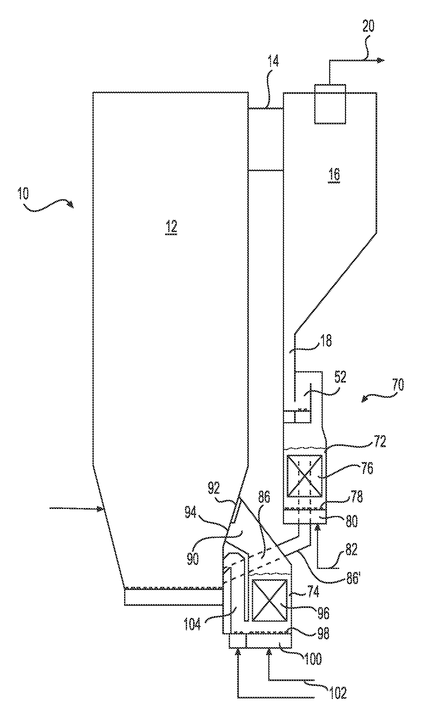
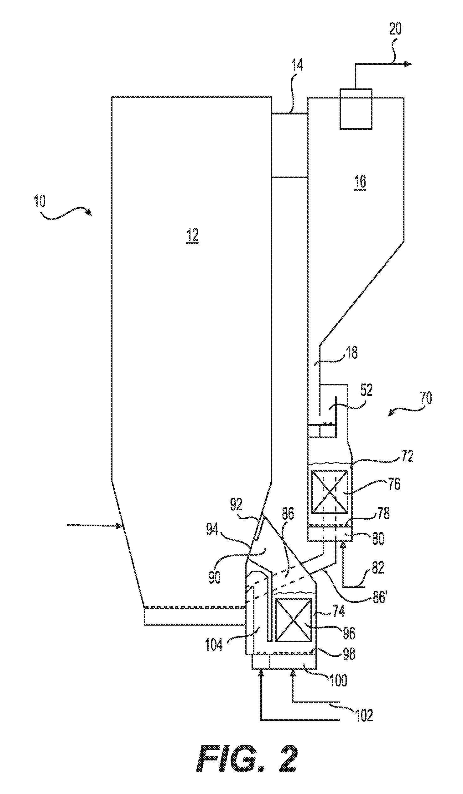
First, since the upper heat exchange chamber is supposed to
discharge the cooled solids to the lower one, the channel between the heat exchange chambers runs between the upper heat exchange chamber and the furnace forcing positioning of the first / upper heat exchange chamber substantially far from the furnace wall. This also means that the solids separator has to be positioned far from the furnace, as the upper heat exchange chamber is normally positioned right below the separator, and supported from the separator.
Second, as the lower heat exchange chamber is supposed to be able to receive all the cooled solids from the upper heat exchange chamber, and possibly, also some additional solids from the internal circulation, it is clear that the volume of the lower heat exchange chamber should at least correspond to the one of the upper heat exchange chamber. As already discussed above in connection with the PCT publication (WO 2007 / 128883 A2), neither the height nor the width (in a direction parallel to the furnace wall) of the lower
heat exchanger can be chosen freely, but both the pressure loss in the
fluidization, and the space occupied by the heat exchange chamber have to be considered. The above consideration results in that the dimensions of the lower heat exchange chamber are substantially equal with the upper one. Thereby, there is very little room in connection with the lower section of the furnace for the equipment necessary for running the boiler, such as, for example, the start-up burner, a temperature measuring device for measuring the lower
furnace temperature, a
pressure measurement device for measuring the bed pressure, and feeds for introducing fuel, bed material, secondary air, additives, recirculated
flue gas (if in use), etc.
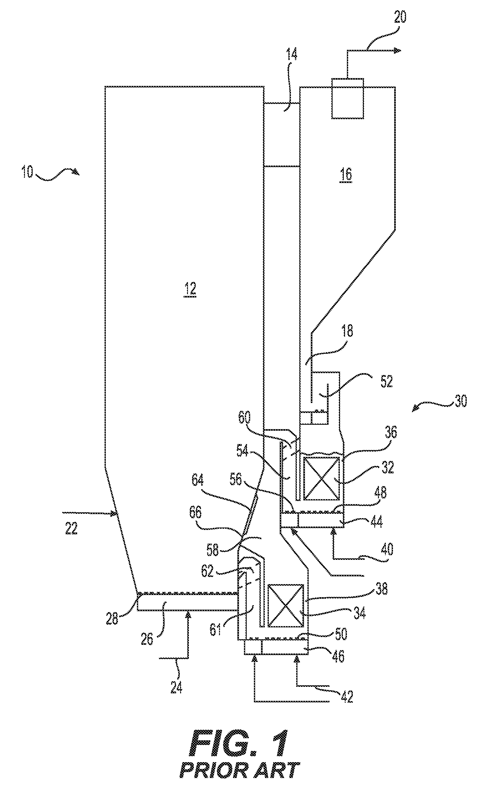
Third, due to the various running alternatives, i.e., control options in the prior art boiler, there are conduits and channels for each alternative. For instance, the upper heat exchange chamber has one inlet from the separator, and several outlet channels and lift channels. One lift channel and outlet channel leading to the lower
heat exchanger, another lift channel and outlet channel leading to the furnace, and overflow channels leading to both the lower heat exchange chamber and to the furnace. In addition to the channels, rather complicated
fluidization means and controllers for adjusting the fluidizations are also required at the bottom of the upper heat exchange chamber. If, and when, the various channels and conduits require
bellows to separate components in different temperatures, the
bellows, again, occupy space, and also increase the costs of the heat exchanger arrangement together with the already numerous channels, conduits, fluidization equipment, and control systems that have been discussed above. And, still further, all of the channels and conduits need to be either made of water / steam tube walls and connected to the rest of the steam / water
system, or made of a
refractory material. Irrespective of the manufacture, this adds to the expenses as constructing the channels of water / steam tube walls or
refractory material is a complicated and time-consuming task.

