Supercharge Your Innovation With Domain-Expert AI Agents!

Load simulator

a simulator and load technology, applied in the field of load simulators, can solve the problems that the detection value obtained by the sensors can deviate from the correct value, and achieve the effect of raising the precision of measured values

Inactive Publication Date: 2016-08-23
DAIHEN CORP
View PDF12 Cites 0 Cited by
  • Summary
  • Abstract
  • Description
  • Claims
  • Application Information

AI Technical Summary

Benefits of technology

The present invention provides a load simulator for calibration of high frequency measurement apparatus in plasma processing apparatus. The load simulator includes electrode plates that are pressed in a predetermined direction to improve accuracy of measured values. By using the load simulator, a calibration parameter can be calculated to correct detected values obtained by the high frequency measurement apparatus. This improves the precision of measured values and ensures accurate plasma processing.

Problems solved by technology

In general, with high frequency measurement apparatuses, the detected values obtained by the sensors can deviate from correct values due to errors in the sensor sensitivity and the like.

Method used


Image

  • Load simulator
  • Load simulator
  • Load simulator

Examples


Embodiment Construction

[0034]A specific description of an embodiment of the present invention will be given below with reference to the attached drawings.

[0035]FIGS. 1 to 5 are diagrams for describing a load simulator based on an embodiment of the present invention.

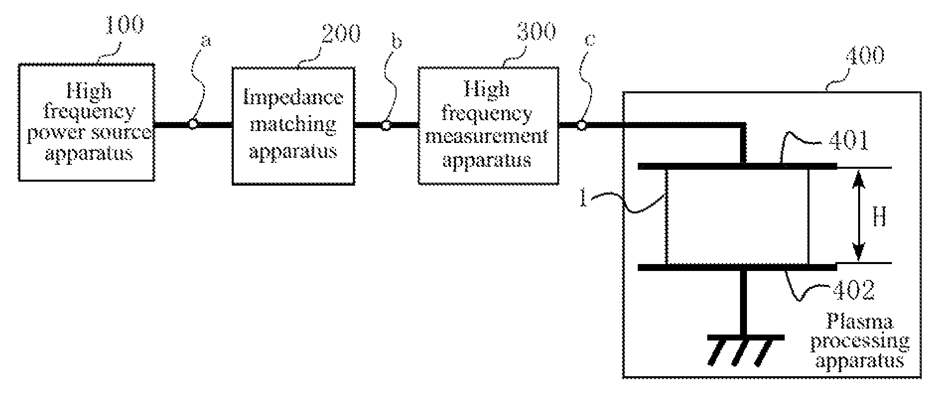
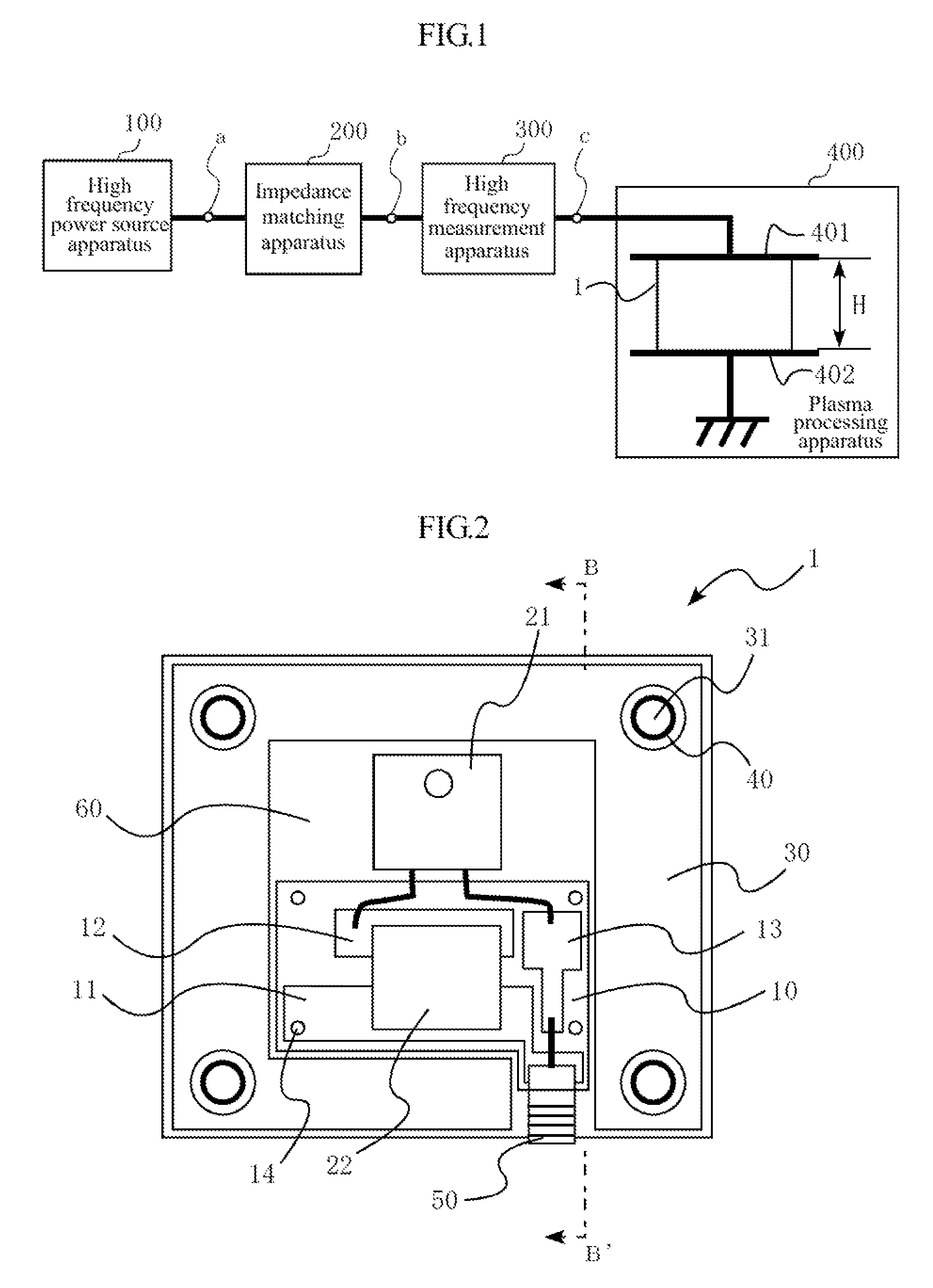
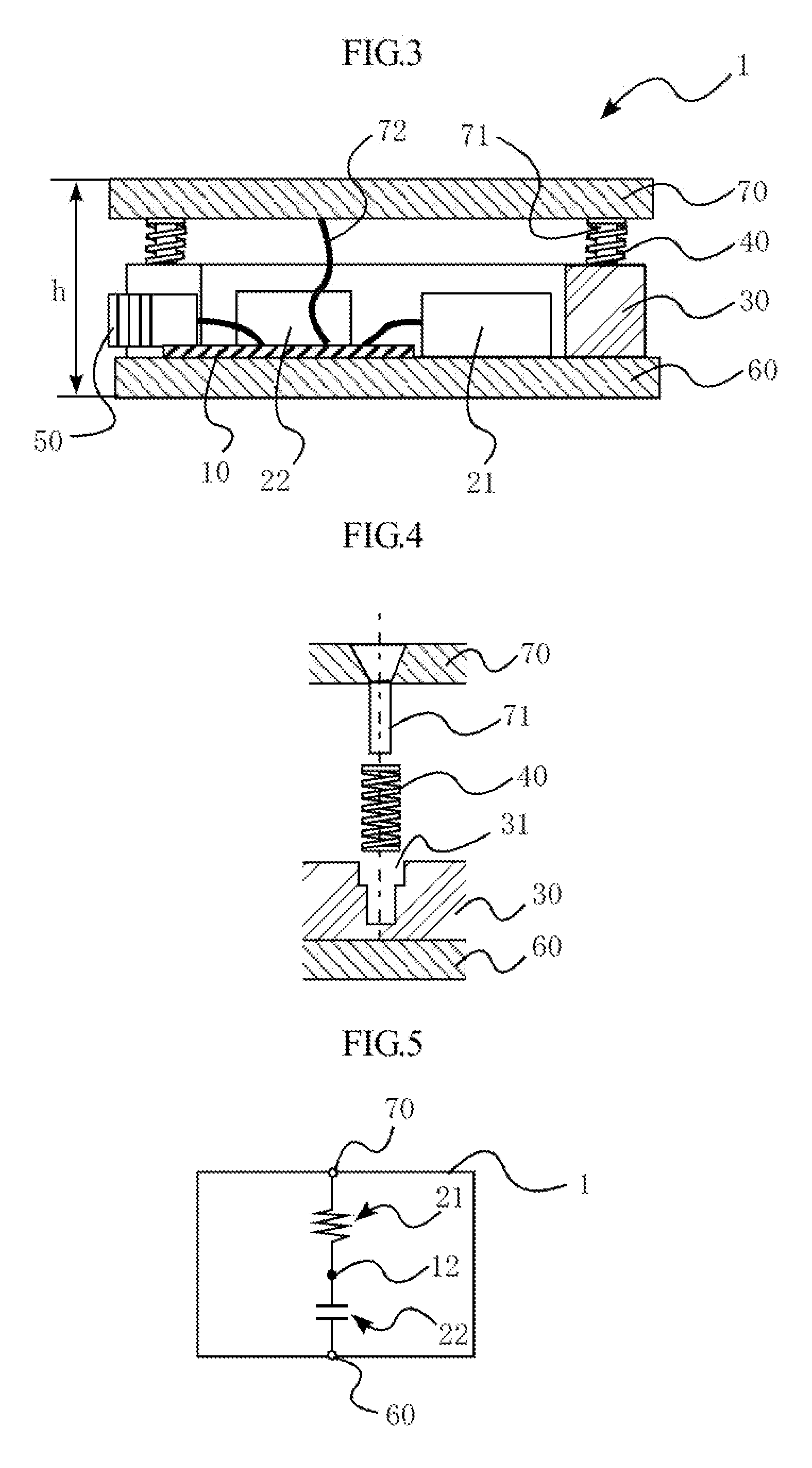
[0036]As shown in FIG. 2, a load simulator 1 includes passive elements such as a resistor 21 and a capacitor 22. The impedance of the load simulator 1 is set to a predetermined value. The load simulator 1 can therefore be used to simulate a load having that impedance value.

[0037]As shown in FIG. 1, the chamber of a plasma processing apparatus 400 is provided with two electrodes, namely a positive electrode 401 and a ground electrode 402. The load simulator 1 is disposed between these two electrodes, and is used to calibrate a high frequency measurement apparatus 300. The high frequency measurement apparatus 300 is connected to an input terminal c of the plasma processing apparatus 400, and a calibration parameter is calculated based on a measur...


PUM


Abstract

A load simulator includes a passive element, two electrode plates that are connected to the passive element, and a bias applier. The bias applier is a coil spring, for example, and is provided between the two electrode plates. The bias applier biases at least one of the two electrode plates in a predetermined direction. The two electrode plates are disposed so as to be substantially parallel with each other, for example, and the bias applier biases the two electrode plates in the direction of separation from each other.

Description

BACKGROUND OF THE INVENTION[0001]1. Field of the Invention[0002]The present invention relates to a load simulator used in a plasma processing system or the like.[0003]2. Description of Related Art[0004]Recent years have seen the development of a plasma processing system in which a workpiece such as a semiconductor wafer or a liquid crystal substrate is processed using a method such as etching. FIG. 8 is a block diagram showing the configuration of a general plasma processing system. The plasma processing system shown in FIG. 8 includes a high frequency power source apparatus 100, an impedance matching apparatus 200, a high frequency measurement apparatus 300, and a plasma processing apparatus 400. The high frequency power source apparatus 100 outputs high frequency power, which is supplied to the plasma processing apparatus 400.[0005]The high frequency measurement apparatus 300 monitors the impedance and the like of the plasma processing apparatus 400 during plasma processing. The h...

Claims


Application Information

Patent Timeline
Patent Type & Authority Patents(United States)
IPC IPC(8): G01P3/54H01J37/32G01P3/66G01R27/28
CPCH01J37/32091H01J37/32935G01R27/28
Inventor TABUCHI, ISAO
Owner DAIHEN CORP
Features
  • R&D
  • Intellectual Property
  • Life Sciences
  • Materials
  • Tech Scout
  • Unparalleled Data Quality
  • Higher Quality Content
  • 60% Fewer Hallucinations
Learn More