Resilient coaxial connector interface and method of manufacture

a coaxial connector and resilient technology, applied in the direction of coupling device connection, waveguide type device, coupling/disconnecting parts, etc., can solve the problems of reducing the electrical performance of the entire rf system, relative weak interconnection retention

Active Publication Date: 2016-08-23
COMMSCOPE TECH LLC
View PDF42 Cites 16 Cited by
  • Summary
  • Abstract
  • Description
  • Claims
  • Application Information

AI Technical Summary

Benefits of technology

[0038]In addition to varying levels of compression force that may be applied by different users, the inventor has also recognized that small variations in interpretation of standardized interface dimensions and / or manufacture methods between different connector manufacturers can lead to variances of the actual contact surface area between mating surfaces and / or result in skewed and / or angled rather than the parallel surface-to-surface or concentric mating. Further, dimensional allowances applied to the interconnection to allow for machining tolerances and / or for ease of interconnection mating may enable random air gaps to arise around the circumference or depth of a rigid interconnection, even when adequate compression levels are applied.
[0060]Coaxial coupling connectors adapted for mating with the standardized connection interface of existing coaxial connectors may enable cost efficient upgrade to new equipment and / or cabling providing the benefit of PIM free interconnections without requiring replacement and / or retrofitting of the entire RF system. Similarly, an RF system utilizing interconnections with a standardized capacitive coupled connector interface has the inherent flexibility of later being easily modified for operation with a conventional electromechanical interconnection should such become desired in view of changes to operating frequencies or the like.

Problems solved by technology

Connector interfaces with flexible outer conductor contact surfaces are known; however, these may have relatively weak interconnection retention and / or additional mechanism such as movable lever actions to apply and / or release bias upon conventional spring finger elements of the contact surfaces to enable tool-less connection and disconnection, for example in “quick connect / disconnect” type connectors.
PIM is an important interconnection quality characteristic, as PIM generated by a single low quality interconnection may degrade the electrical performance of an entire RF system.

Method used


Image

  • Resilient coaxial connector interface and method of manufacture
  • Resilient coaxial connector interface and method of manufacture
  • Resilient coaxial connector interface and method of manufacture

Examples


Embodiment Construction

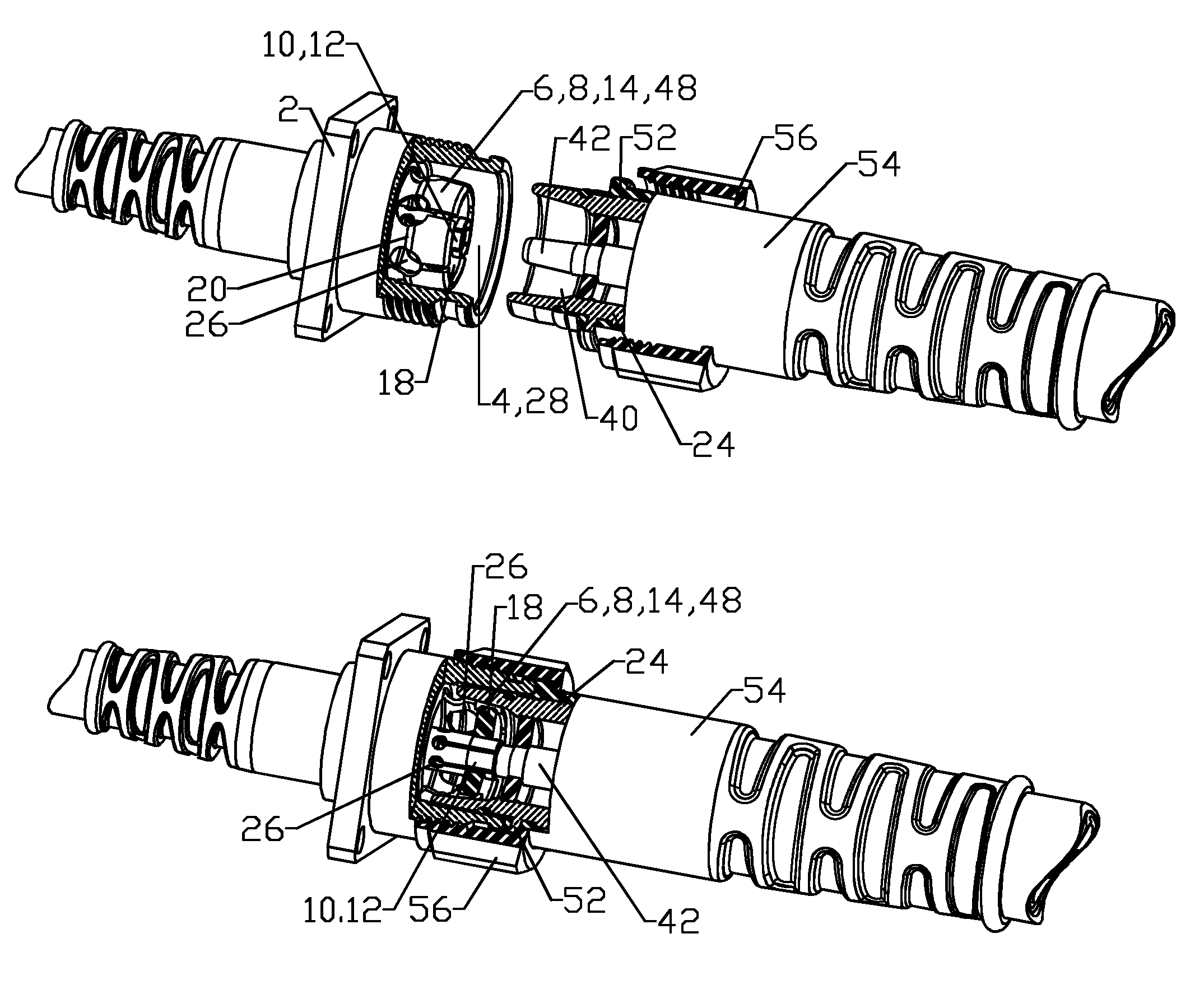
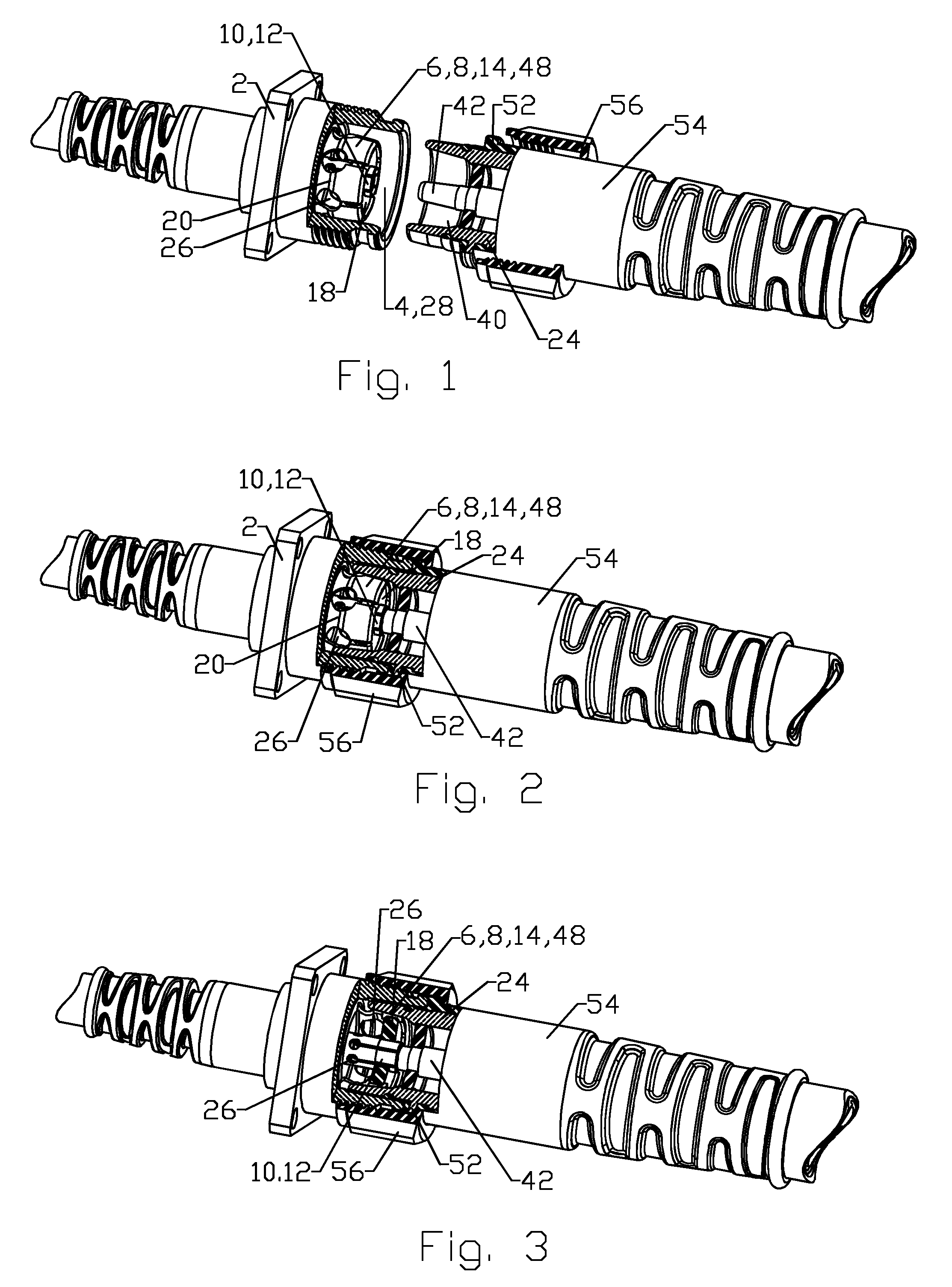
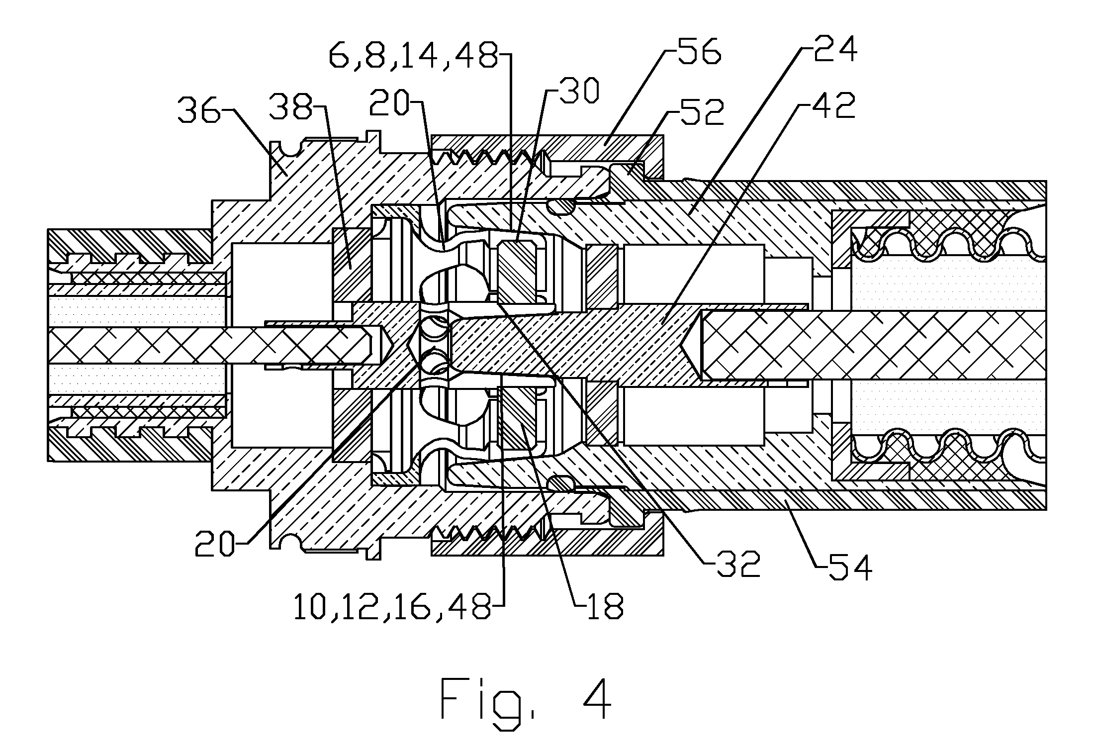
[0036]The inventor has recognized that PIM may be generated at, in addition to the interconnections between the inner and outer conductors of a coaxial cable and each coaxial connector, the electrical interconnections across the connector interfaces of mating coaxial connectors. The inventor has analyzed PIM generation in prior connection interfaces and realized that rigid connection interfaces may generate varying levels of PIM depending upon contact mating surface conformity and / or environmental factors such as temperature or vibration, which may induce shifts of the mating surfaces with respect to one another.

[0037]Dielectric surface coatings and / or spacers that may be present between contact surfaces may degrade over time due to compression levels that may be applied and / or mechanical wear between the shifting mating surfaces, resulting in altered electrical characteristics of the mating surface interconnections, such as capacitance, that may be required to achieve capacitive ra...


PUM

PropertyMeasurementUnit
resilientaaaaaaaaaa
outer diameteraaaaaaaaaa
inner diameteraaaaaaaaaa

Abstract

A resilient connector interface provided with an outer conductor contact with a plurality of outer conformable members and an inner conductor contact with a plurality of inner conformable members. The outer conformable members provided with an outer conductor coupling surface on an outer diameter and the inner conformable members provided with an inner conductor coupling surface on an inner diameter. An alignment portion is provided at a proximal end of the outer conformable member. The alignment portion may be sinuous with respect to a longitudinal axis of the outer conformable member. An elastic bias member is positioned between the outer conformable members and the inner conformable members biasing the outer conformable members outward and the inner conformable members inward. The outer conductor coupling surface and the inner conductor coupling surface may be covered with a dielectric material to form a capacitive coupling interconnection.

Description

CROSS REFERENCE TO RELATED APPLICATIONS[0001]This application is a continuation-in-part of commonly owned co-pending U.S. Utility patent application Ser. No. 14 / 074,016, titled “COAXIAL CONNECTOR WITH CAPACITIVELY COUPLED CONNECTOR INTERFACE AND METHOD OF MANUFACTURE” filed 7 Nov. 2013 by Ronald Alan Vaccaro, Jeffrey D Paynter and Kendrick Van Swearingen, hereby incorporated by reference in its entirety, which is a continuation-in-part of commonly owned U.S. Utility patent application Ser. No. 13 / 673,084, titled “CONNECTOR WITH CAPACITIVELY COUPLED CONNECTOR INTERFACE” filed 9 Nov. 2012 by Kendrick Van Swearingen, Ronald Alan Vaccaro, James P. Fleming and Jeffrey D Paynter, issued as U.S. Pat. No. 8,622,768 on 7 Jan. 2014 and hereby incorporated by reference in its entirety.BACKGROUND[0002]1. Field of the Invention[0003]This invention relates to electrical cable connectors. More particularly, the invention relates to Radio Frequency (RF) coaxial connectors with resilient conductor c...

Claims


Application Information

Patent Timeline
Patent Type & Authority Patents(United States)
IPC IPC(8): H01R11/22H01R13/11H01R13/622H04B5/00H01R13/15H01R24/44H01P5/02H01R13/17H01R13/18
CPCH04B5/0012H01R13/622H01R13/15H01R24/44H01P5/026H01R13/17H01R13/18Y10T29/49123
Inventor VAN SWEARINGEN, KENDRICK
Owner COMMSCOPE TECH LLC
Why Eureka
Try Eureka