Live 3D X-ray viewing

a 3d x-ray and live technology, applied in the field of 3d x-ray imaging, can solve the problems of fatigue and headache, discomfort, and inability to provide 3d images in real time, and achieve the effect of preventing fatigue and good depth resolution

Active Publication Date: 2016-08-30
KONINKLJIJKE PHILIPS NV
View PDF15 Cites 7 Cited by
  • Summary
  • Abstract
  • Description
  • Claims
  • Application Information

AI Technical Summary

Benefits of technology

[0006]X-ray stereo imaging can be used for two main purposes: viewing and extraction of positional / directional information. For information extraction (e.g. catheter tracking or registration), it is favorable to have a large distance between the two X-ray spots, which allows good resolution of depth. For 3D stereo viewing, which can give depth information to the viewer in an intuitive way (ease of use), it is important to provide optimum 3D viewing comfort to prevent fatigue.
[0007]It can be seen as an objective of the invention to provide a system and method for live 3D x-ray viewing with improved viewing comfort.

Problems solved by technology

However, such a 3D image may not be provided in real-time.
However, 3D stereo viewing can cause fatigue and headache due to a variety of cases, including an incorrect or unnatural perspective, the vergence / accommodation conflict, visual artifacts like flicker or resolution loss, and wearing 3D glasses.
For example, a discomfort may be caused by a mismatch between the distance to the plane (screen) at which the eyes are focused and the distance to the point at which they converge.

Method used


Image

  • Live 3D X-ray viewing
  • Live 3D X-ray viewing
  • Live 3D X-ray viewing

Examples


Embodiment Construction

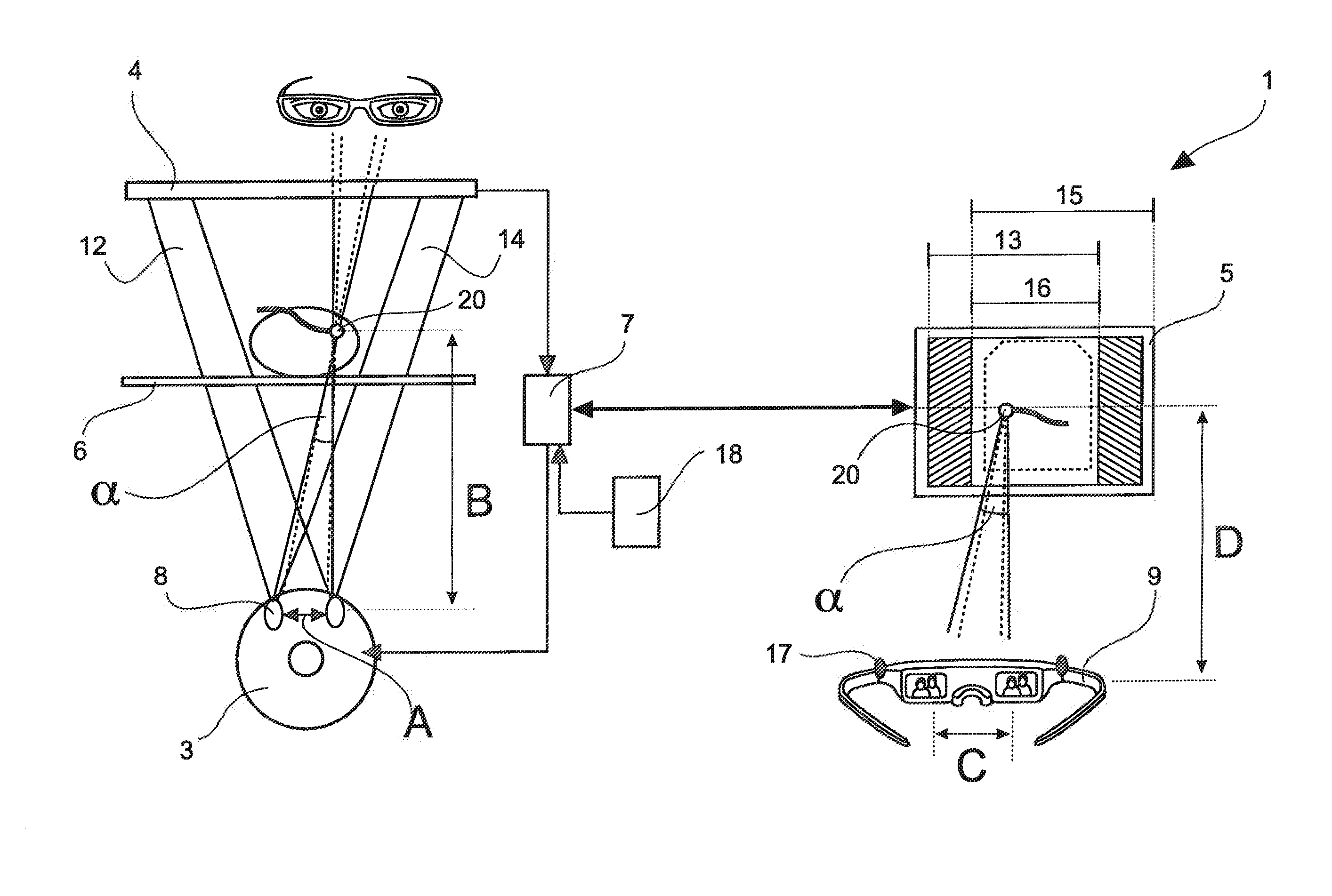
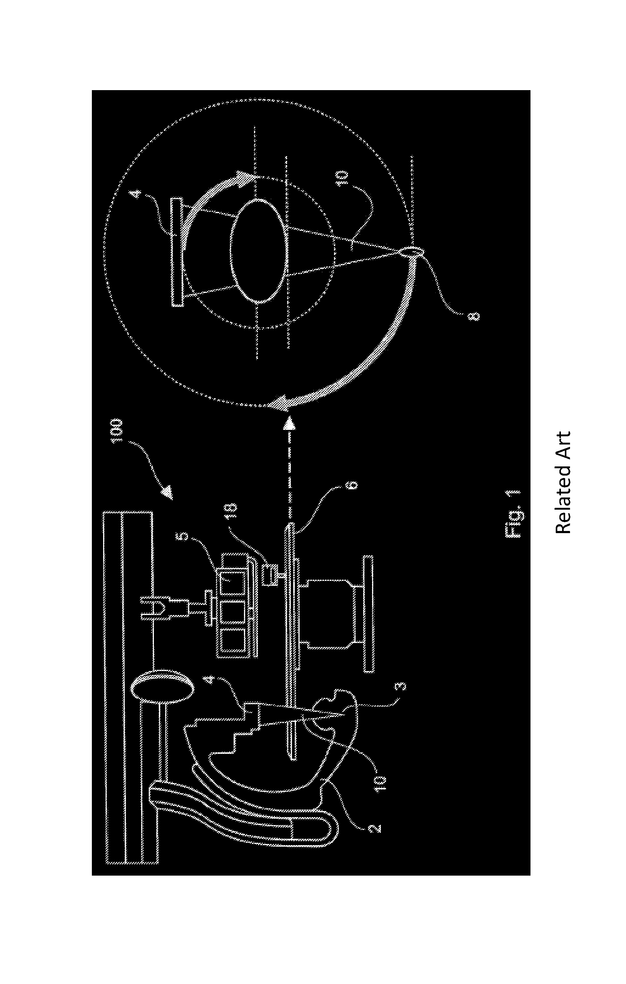
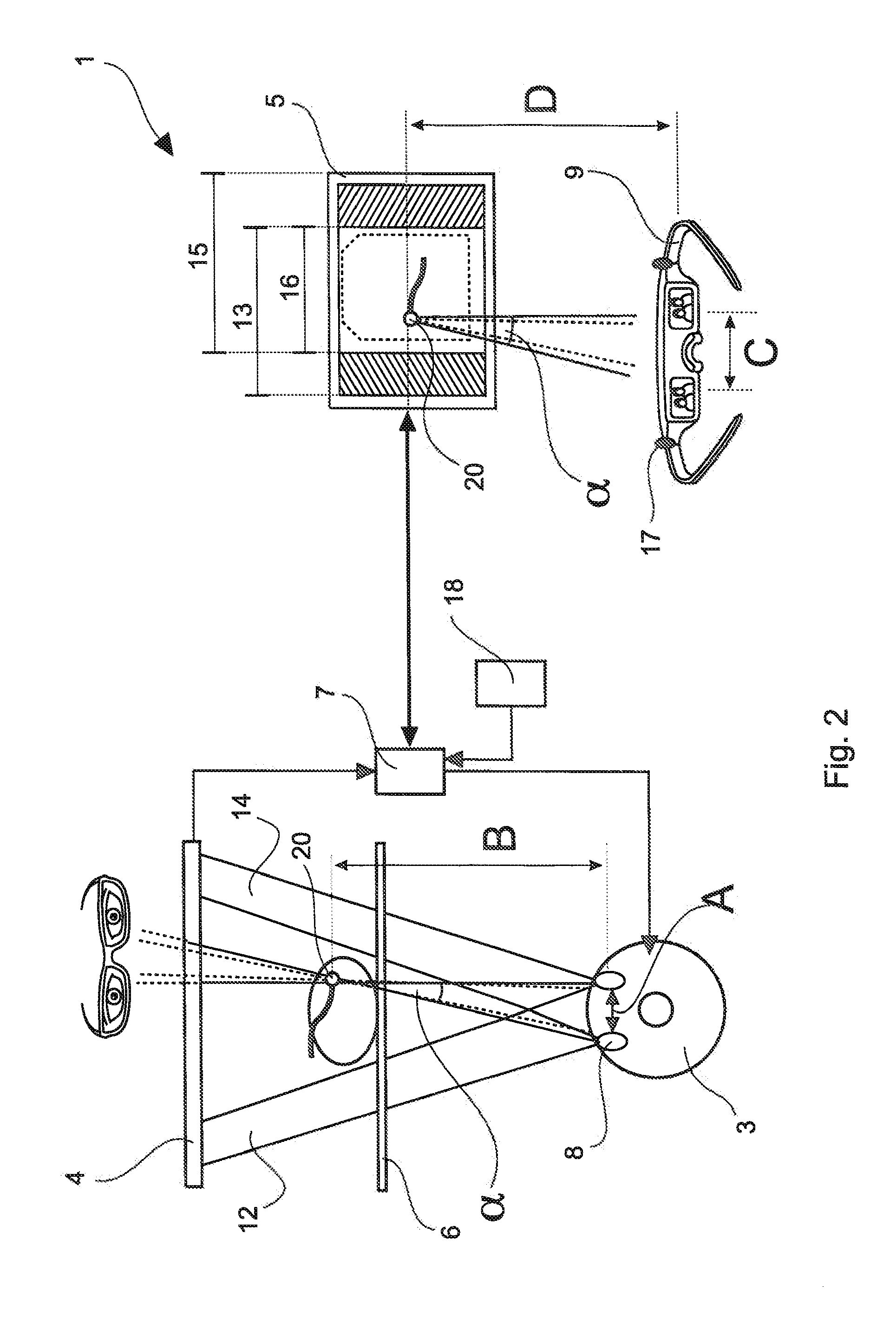
[0036]FIG. 2 shows a system 1 for live 3D x-ray viewing according to the invention. It will be understood that the system 1 is similar to the system 100 shown in FIG. 1, in that the system 1 comprises a C-arm 2 with an x-ray source 3 and an x-ray detector 4, a monitor 5 and a table 6. The system 1 differs from the system 100 in that the x-ray source 3 includes two focal spots 8 instead of only one. Further shown in FIG. 2 is a processing unit 7, an input device 18 and 3D glasses 9 with trackable elements 17.

[0037]To achieve a live 3D x-ray viewing in accordance with the invention, trackable LEDs or reflectors 17 may be arranged on the 3D glasses 9 and for example an average eye separation C may be used or the viewer's interpupillary distance may be measured (or eye tracking may be used). Additionally, the live 3D stereo acquisition / viewing conditions according to the viewer's head position may be adjusted with respect to the screen of the monitor 5.

[0038]In particular, an improved X...


PUM


Abstract

System for live 3D x-ray viewing comprising an x-ray source, an x-ray detector, a processing unit, a monitor and means for detecting viewer's eyes, wherein the x-ray source and the x-ray detector are arranged at a movable C-arm. The x-ray source comprises two focal spots, wherein a separation of the two focal spots is adjustable so that the image acquisition angle between the two focal spots matches the viewing angle between the two eyes.

Description

CROSS-REFERENCE TO PRIOR APPLICATIONS[0001]This application is the U.S. National Phase application under 35 U.S.C. §371 of International Application Serial No. PCT / IB2012 / 054759, filed on Sep. 13, 2012, which claims the benefit of U.S. Application Ser. No. 61 / 535,506, filed on Sep. 16, 2011. These applications are hereby incorporated by reference herein.FIELD OF THE INVENTION[0002]The invention relates to 3D x-ray imaging. In particular, the invention relates to a system and method for live 3D x-ray viewing. Further, the invention relates to a computer program that implements the method.BACKGROUND OF THE INVENTION[0003]A known possibility of achieving a 3D volume image is shown in FIG. 1. The system 100 in FIG. 1 comprises a C-arm 2 with an x-ray source 3 and an x-ray detector 4, a monitor 5, and a table 6. The C-arm 2, i.e. one focal spot 8 of the x-ray source 3 together with the x-ray detector 4, rotates around the object of interest (indicated by the curved arrows) and a series o...

Claims


Application Information

Patent Timeline
Patent Type & Authority Patents(United States)
IPC IPC(8): A61B6/02A61B6/03A61B6/00A61B6/12A61B17/00
CPCA61B6/022A61B6/4028A61B6/4441A61B6/466A61B6/469A61B6/545A61B6/035A61B6/4021A61B6/46A61B6/12A61B6/467A61B6/589A61B2017/00216A61B2090/368A61B2090/376
Inventor STEINHAUSER, HEIDRUNMURDOCH, MICHAEL JOHNPRINSEN, PETER
Owner KONINKLJIJKE PHILIPS NV
Why Eureka
Try Eureka