Sheet manufacturing apparatus and defibrating unit

a technology of defibrillator and manufacturing apparatus, which is applied in the field of sheet manufacturing apparatus and defibrillator, can solve the problems of difficult to reduce the size of the sheet manufacturing apparatus, difficult to meet current energy saving demands, and manufacturing completely with dry type technology, so as to effectively feed the defibrillator and suppress the generation of transfer problems

Active Publication Date: 2016-08-30
SEIKO EPSON CORP
View PDF25 Cites 8 Cited by
  • Summary
  • Abstract
  • Description
  • Claims
  • Application Information

AI Technical Summary

Benefits of technology

[0011]According to this sheet manufacturing apparatus, it is possible to effectively feed the defibration object toward the rotor since the feeding blade which generates a flow of air is provided on the input section side in the defibrating unit. Due to this, it is possible to prevent the defibration object building up on the input section side. In addition, since it is possible to generate a flow of air from the upstream side to the downstream side of the distribution path of the defibration object by providing the feeding blade, it is possible to generate a flow of air which is stronger than a flow of air which is generated using only the rotor and it is possible to suppress transfer problems being generated in the defibrating unit. As a result, it is possible to stably manufacture sheets which are strong in practice. Here, the sheet manufacturing apparatus has the following effects compared to a case where the feeding blade is provided on the output side for defibrated material. In a case where the feeding blade is provided on the output side for defibrated material, it is easy to transfer materials in a fibrous form at the output side for defibrated material, but the flow of air with regard to the materials (for example, paper) at the input side for defibrated material and it is difficult to transfer materials. In contrast to this, by providing the feeding blade on the input side for defibrated material, it is possible for the flow of air to work with regard to the material in a state which is difficult to transfer and feeding is possible by the feeding blade hitting up against the materials. As a result, it is better for the feeding blade to be on the input section side instead of the output section side.
[0029]According to this defibrating unit, it is possible to effectively feed the defibration object toward the rotor since the feeding blade which generates a flow of air is provided on the input section side. In addition, by providing the feeding blade, it is possible to generate a flow of air which is stronger than a flow of air which is generated using only the rotor. Due to this, it is possible to suppress transfer problems being generated in the defibrating unit.

Problems solved by technology

In addition, it is difficult to reduce the size of a sheet manufacturing apparatus since a large amount of equipment for installations for water, electrical power, water discharge, and the like are necessary.
As a result, it is difficult to respond to current demands for energy saving, protecting the environment, and the like.
As a sheet manufacturing method to replace the manufacturing method in the prior art as above, there are expectations for a method which uses very little or no water which is referred to as a dry type, but a technique for manufacturing completely with a dry type, from raw materials to sheets as the final product, has not yet been sufficiently established in the manufacturing of sheets at the current point in time.
However, in the technique described in Japanese Unexamined Patent Application Publication No. 2007-144819, there is a concern that transfer problems will be generated in a defibrating unit with a system where the defibration object is transported by relying on only the flow of air which is generated by rotating of the rotating unit.
In a case where the feeding blade is provided on the output side for defibrated material, it is easy to transfer materials in a fibrous form at the output side for defibrated material, but the flow of air with regard to the materials (for example, paper) at the input side for defibrated material and it is difficult to transfer materials.
A feeding effect and a crushing effect are reduced since a force in a direction of returning works with regard to inputting from the input section in a case where the feeding blade and the input section are in the same position in the extending direction of the central rotation axis and it is not possible for the defibration object to come into contact with the feeding blade when the input section is arranged closer to the rotor in the extending direction of the central rotation axis with regard to the feeding blade.

Method used


Image

  • Sheet manufacturing apparatus and defibrating unit
  • Sheet manufacturing apparatus and defibrating unit
  • Sheet manufacturing apparatus and defibrating unit

Examples


Embodiment Construction

[0044]Several embodiments of the present invention will be described below. The embodiments described below will be described as examples of the invention. The invention is not limited to the following embodiments and various modifications, which are carried out within a scope which does not depart from the gist of the invention, are included. Here, none of the configurations described below limit the configuration which is essential for the invention.

1. Sheet Manufacturing Apparatus

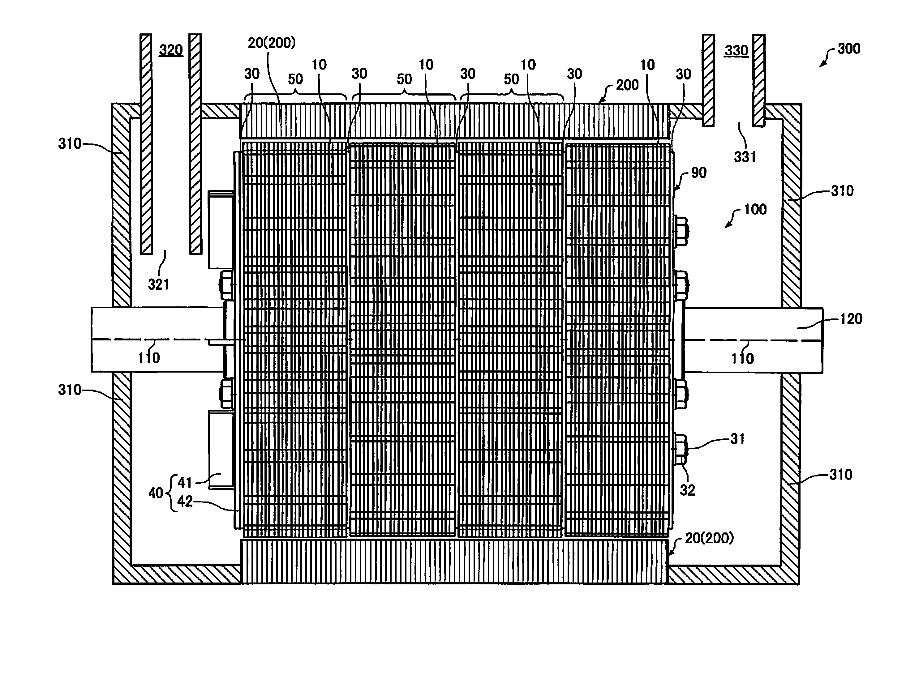
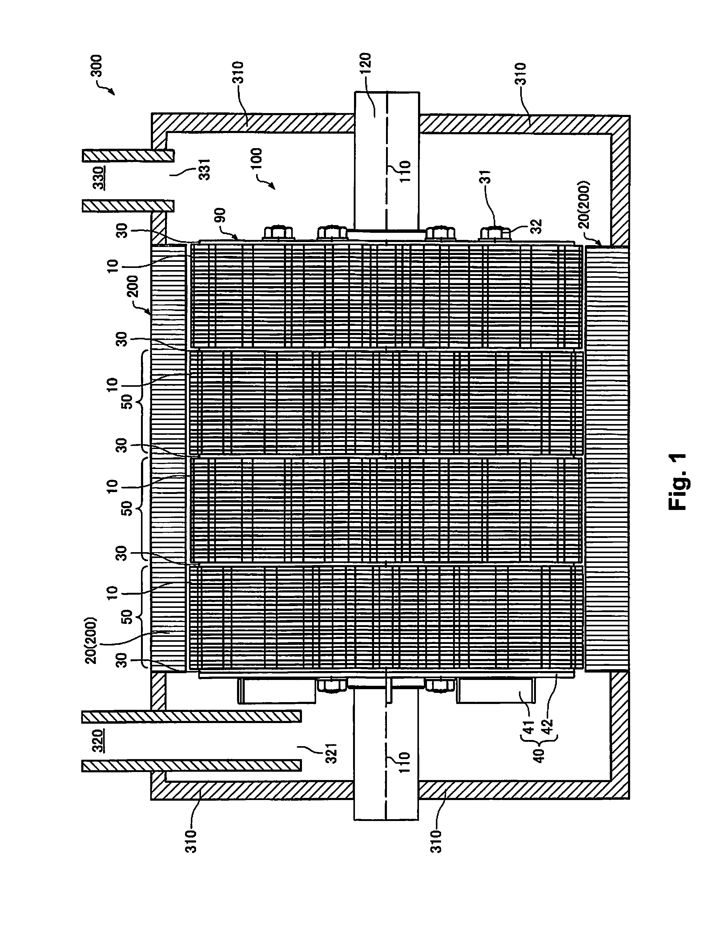
[0045]A sheet manufacturing apparatus 1000 according to the present embodiment will be described below by appropriately referencing FIGS. 1-10.

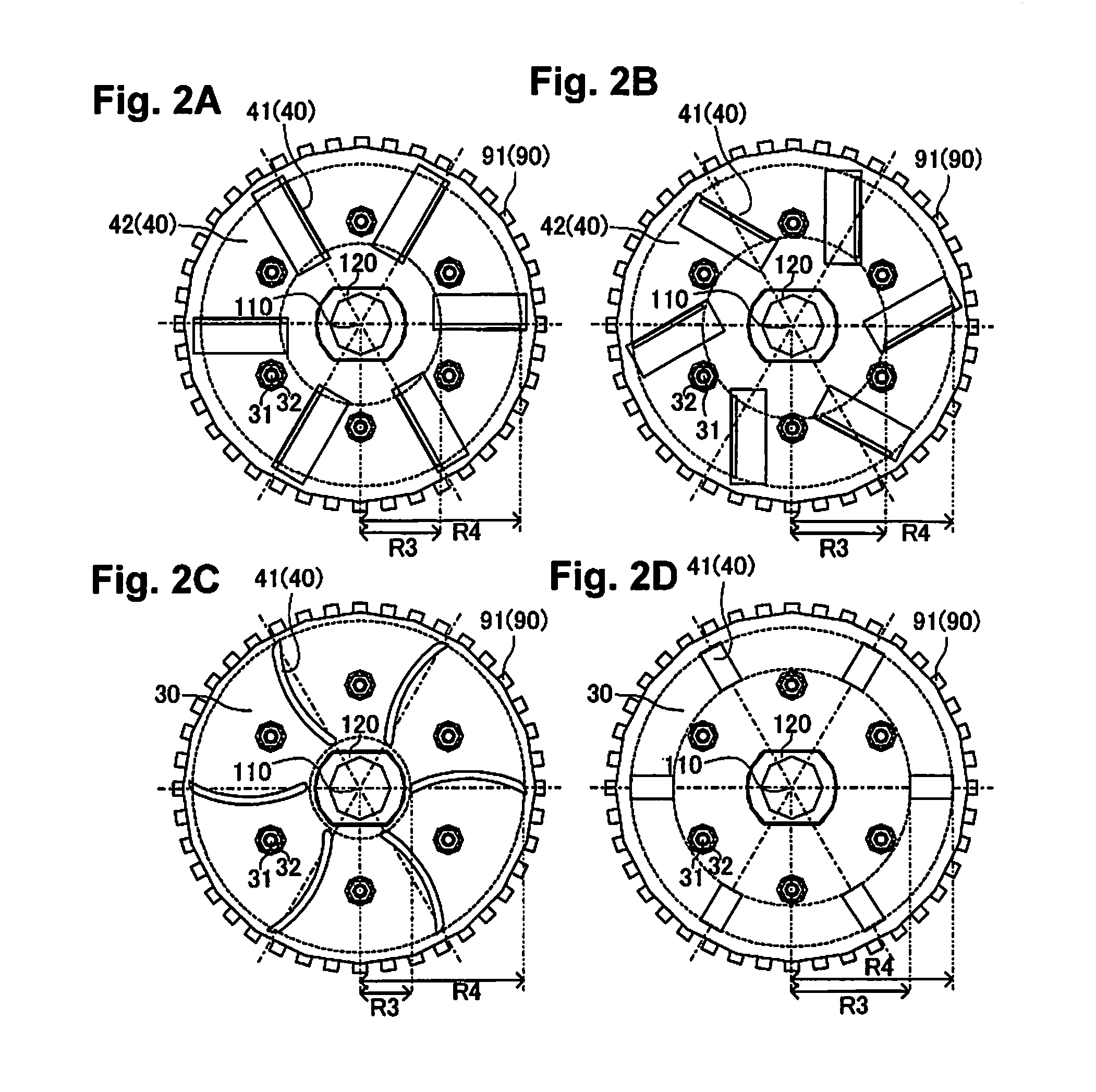
[0046]FIG. 1 is a schematic diagram illustrating a partial cross section of a defibrating unit 300. FIGS. 2A to 2D are schematic diagrams illustrating a rotating unit 100 viewed from the extending direction of a central rotation axis 110. FIG. 3 and FIG. 4 are schematic diagrams illustrating a main portion of the defibrating unit 300 viewed from a direction which ...


PUM

PropertyMeasurementUnit
circumferenceaaaaaaaaaa
sizeaaaaaaaaaa
outer circumferenceaaaaaaaaaa

Abstract

The sheet manufacturing apparatus includes the defibrating unit configured to carry out a dry-type defibrating process on defibration object by rotating a rotating unit, and manufactures sheets by accumulating and heating at least a portion of defibrated material on which the dry-type defibrating process is carried out. The rotating unit includes a rotor that has a plurality of protruding sections on an outer circumference of the rotor, and a feeding blade configured to generate a flow of air and arranged on a side section of the rotor on a side of the input section for the defibration object.

Description

CROSS-REFERENCE TO RELATED APPLICATIONS[0001]This application claims priority to Japanese Patent Application No. 2013-211678 filed on Oct. 9, 2013. The entire disclosure of Japanese Patent Application No. 2013-211678 is hereby incorporated herein by reference.BACKGROUND[0002]1. Technical Field[0003]The present invention relates to a sheet manufacturing apparatus and a defibrating unit.[0004]2. Related Art[0005]A process (disintegrating process), where a material which is a raw material is changed into fiber before the process of being changed into sheets, is typically performed in the field of sheet manufacturing. A wet system which uses a large amount of water is currently mainstream as the disintegrating process. Accordingly, processes such as water removal and drying are necessary after the sheets are formed. In addition, it is difficult to reduce the size of a sheet manufacturing apparatus since a large amount of equipment for installations for water, electrical power, water dis...

Claims


Application Information

Patent Timeline
Patent Type & Authority Patents(United States)
IPC IPC(8): D21D5/18D21B1/06B02C4/10B02C4/30B02C4/28
CPCB02C4/10B02C4/286B02C4/30D21D5/18D21B1/06B02C18/141B02C18/146B29B15/00B29L2007/008D21H17/20
Inventor HIGUCHI, NAOTAKAYAMAGAMI, TOSHIAKIABE, NOBUMASA
Owner SEIKO EPSON CORP
Why Eureka
Try Eureka