Comb structure for a disk drive suspension piezoelectric microactuator operating in the D33 mode, and method of manufacturing the same

Active Publication Date: 2016-08-30
MAGNECOMP
View PDF12 Cites 7 Cited by
  • Summary
  • Abstract
  • Description
  • Claims
  • Application Information

AI Technical Summary

Benefits of technology

[0019]Another advantage of the invention is that encapsulation is not needed to prevent PZT particle shed. The microactuator assembly is composed of individual PZT elements that are sintered ceramic. Because the device including its edges is sintered, the device does not have sawed edges as does a microactuator that has been sawn from a conventional bulk PZT wafer. Such sawed edges are porous and have stressed and segmented partial grains exposed, which leaves them prone to particulate shed if those exposed edges are not encapsulated by epoxy or a similar encapsulant. Particles that have been shed from a PZT into a suspension can damage the surface of the magnetic data disk, possibly even leading to disastrous failure of the disk drive. Accordingly, in conventional PZT microactuators the sawn edges must be encapsulated such as by an encapsulating polymer applied around the edges.
[0020]The individual PZT devices of the present invention also have small electrode gaps compared to certain bender PZT devices. This will allow for small driving voltages while still achieving high stroke lengths. It is also believed that the microactuators will exhibit less out-of-plane deflection. The invention additionally anticipates the forming of raised or recessed features such as mechanical dimples, ribs or castellations either by forming or altered metal thickness of the electrodes to further

Problems solved by technology

PZT microactuators of this type are complex to mechanically and electrically integrate into a suspension, requiring a challenging sequence of steps to terminate the PZT often from opposing sides and multiple applications of both conductive and structural adhesives that mus

Method used


Image

  • Comb structure for a disk drive suspension piezoelectric microactuator operating in the D33 mode, and method of manufacturing the same
  • Comb structure for a disk drive suspension piezoelectric microactuator operating in the D33 mode, and method of manufacturing the same
  • Comb structure for a disk drive suspension piezoelectric microactuator operating in the D33 mode, and method of manufacturing the same

Examples


Embodiment Construction

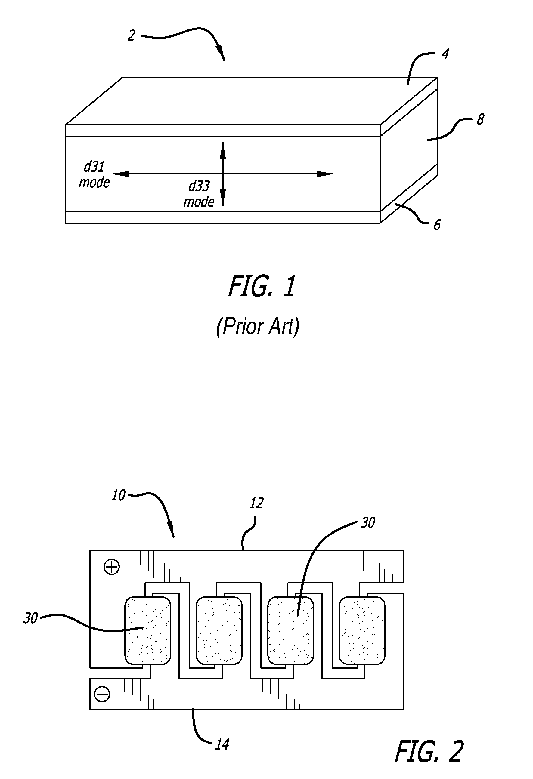
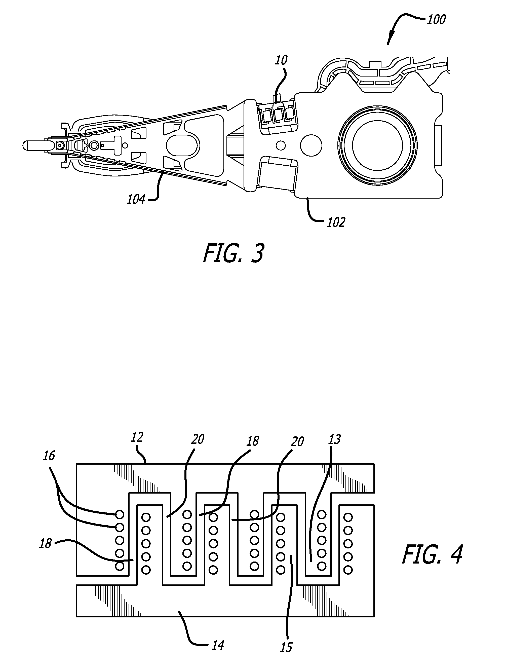
[0048]FIG. 2 is a top plan view of a microactuator assembly 10 according to an exemplary embodiment of the present invention, and FIG. 3 is a top plan view of a suspension assembly 100 in which the microactuator assembly 10 of FIG. 2 is integrated thereto such as by in situ forming integral stainless steel parts of the suspension or by later affixing. It will be understood that FIG. 2 is illustrative only. In the suspension 100 as shown, microactuator assembly 10 is located on the base plate 102. Alternatively, generally speaking microactuator assembly 10 could be located on load beam 104, on or at the gimbal area, or in any other location on which a microactuator motor can be used to effect fine movements of the read / write head carried by the suspension assembly.

[0049]FIG. 4 is a top plan view of a patterned electrode sheet of the microactuator assembly 10 of FIG. 2 before the piezoelectric elements 30 are added. The process begins using a sheet of stainless steel that will be call...


PUM


Abstract

A microactuator assembly is formed by depositing PZT material over electrode gaps, the electrode gaps being defined by the spaces between interleaved fingers of metal that define alternating plus and minus electrodes. The PZT material is hardened and poled. The PZT material may be deposited and poled either as isolated islands of PZT material across respective electrode gaps, or as a continuous sheet of PZT material with localized areas of that material being poled and then activated. The individual PZT elements are arranged such that successive PZT elements extend in the same direction as across the electrode gaps. The resulting microactuator assembly acts in the d33 direction of the PZT elements. The electrodes have raised or recessed features such as ribs or castellations, with the PZT material mating with those features, thus anchoring the PZT material to the electrodes.

Description

CROSS-REFERENCE TO RELATED APPLICATIONS[0001]This application claims priority from provisional patent application No. 61 / 940,812 filed Feb. 17, 2014.BACKGROUND OF THE INVENTION[0002]1. Field of the Invention[0003]This invention relates to the field of microactuators for disk drive suspensions. More particularly, this invention relates to the field of a disk drive suspension piezoelectric microactuator assembly having a comb structure and operating in the d33 mode, and a method of manufacturing and integrating such a microactuator motor assembly.[0004]2. Description of Related Art[0005]Dual stage actuated (DSA) suspensions for disk drives are known. DSA suspensions employ a standard voice coil motor (VCM) or similar primary actuator which moves the entire suspension arm, and in addition they employ a second actuator referred to as a microactuator located on the suspension arm itself. The microactuator moves only a portion of the suspension arm depending on the exact location of the m...

Claims


Application Information

Patent Timeline
IPC IPC(8): G11B5/54G11B5/48
CPCG11B5/4873G11B5/483G11B5/4833
Inventor SCHREIBER, CHRISTOPHERDUNN, CHRISTOPHERHAHN, PETEREE, KUEN CHEE
Owner MAGNECOMP
Why Eureka
Try Eureka