
Measurement transducer for process instrumentation, and method for monitoring the state of its sensor

a technology of measurement transducer and process instrument, applied in the direction of instruments, etc., to achieve the effect of reliable and low cos

Active Publication Date: 2016-09-06
SIEMENS AG
View PDF10 Cites 1 Cited by
  • Summary
  • Abstract
  • Description
  • Claims
  • Application Information

AI Technical Summary

Benefits of technology

[0008]In view of the foregoing, it is an object of the invention to provide a measurement transducer for process instrumentation, in which the state of a sensor can be monitored for tears or breakages in the sensor or in supply lines in a reliable and low cost manner.
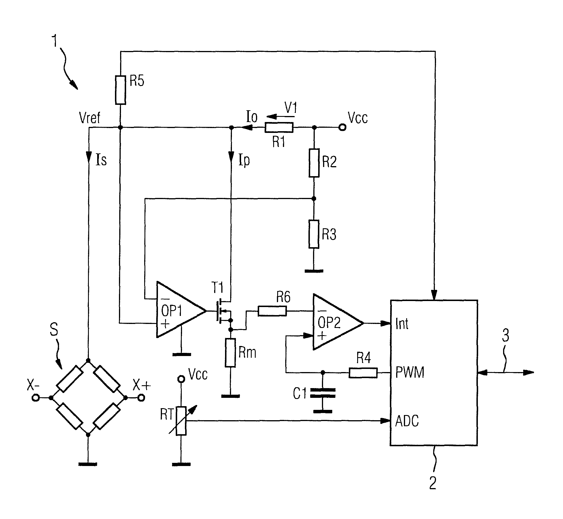
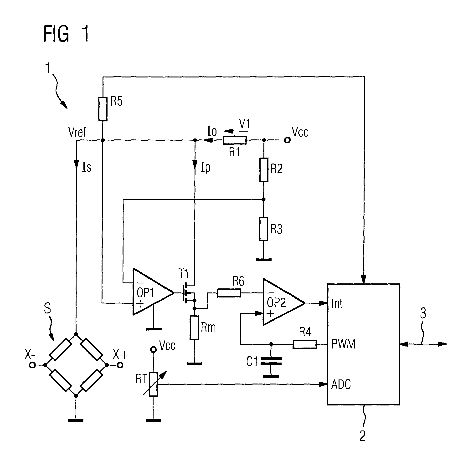
[0010]The disclosed invention is thus advantageous in that a sensor, which is provided to detect a physical or chemical quantity in a measurement transducer, can be monitored for changes in a particularly simple and low cost manner, where the changes are associated, for instance, with the formation of a crack in the substrate or a wire breakage. In such cases, it may occur that a crack formation in the substrate already results in a detectable change in the current adjusted by the cross regulator and flowing in parallel to the sensor, while in the sensor only a creeping change to its property used to generate the measuring signal and thus a displacement of the measured value, a so-called drifting, is caused, which expresses itself solely as an error in the measured value and could not be recognized as a fault without using the cross regulator with current evaluation. The reliability of the measured values provided by the measurement transducer is thus also improved. If an error occurs, which is recognized for instance as excessive current, the measurement transducer outputs a fault message and a process, in which the measurement transducer is used, can be brought into a safer state if necessary. The number of possible errors, which result in a safer state, i.e., the “Safe Failure Fraction (SFF)” is thus increased.
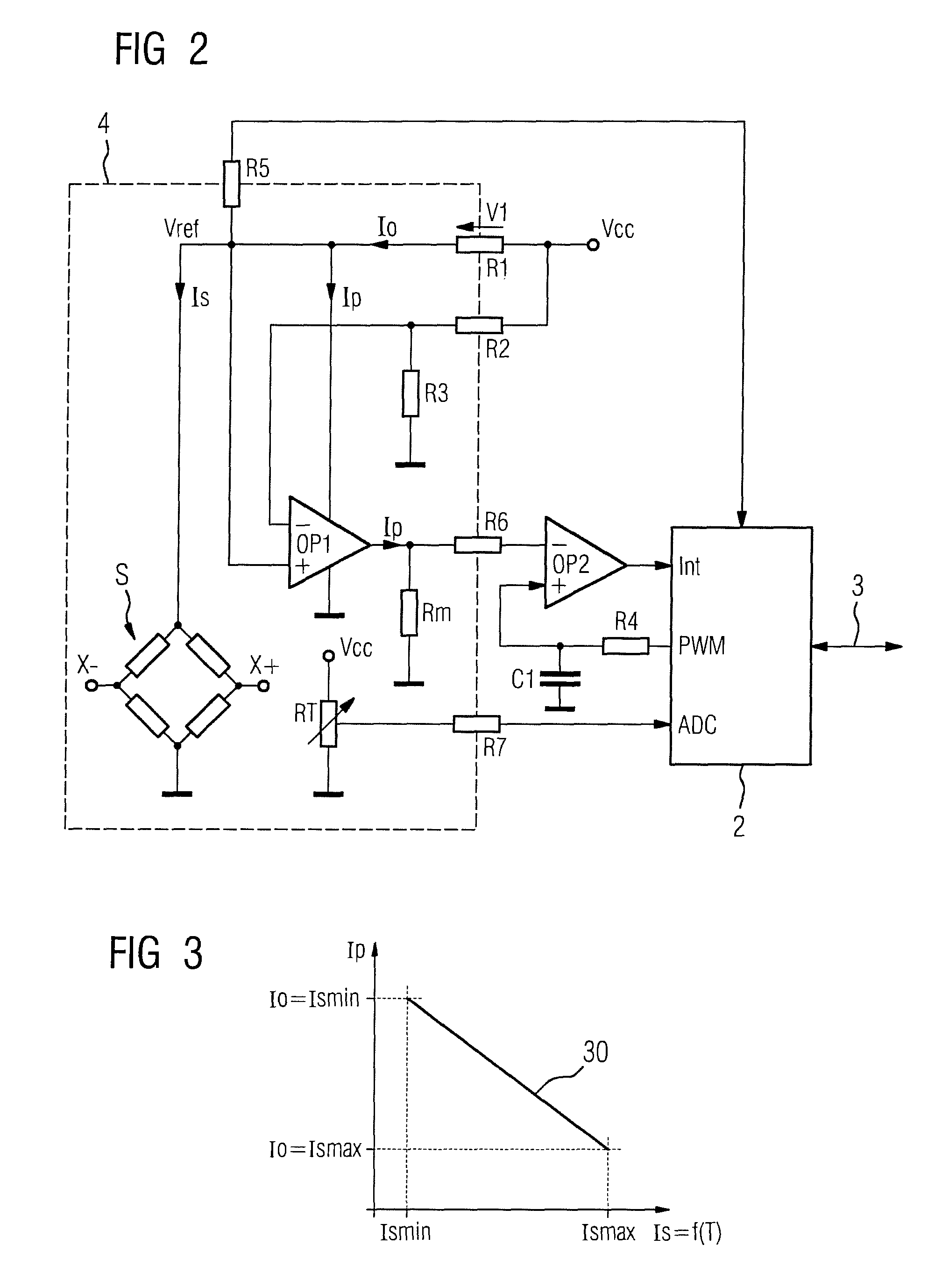
[0013]With a particularly advantageous embodiment of the invention, only a comparatively small current flowing in parallel to the sensor is adjusted by the cross regulator with an intact sensor and a maximum current consumption of the sensor. If a current which is smaller by an order of magnitude for instance than with a minimum current consumption of the sensor is adjusted, the overall current consumption is thus advantageously only insignificantly increased by extending the cross regulator. This has a favorable effect on the current consumption of the measurement transducer.
[0015]An analog-digital converter is usually provided to convert the measuring signal into a digital measured value. In order to improve the measuring accuracy of the measurement transducer, it is advantageous to guide the supply voltage of the sensor to its reference voltage input. This allows for a highly precise ratiometric measurement, which is independent of small fluctuations in the supply voltage of the sensor.

Problems solved by technology

In such cases, it may occur that a crack formation in the substrate already results in a detectable change in the current adjusted by the cross regulator and flowing in parallel to the sensor, while in the sensor only a creeping change to its property used to generate the measuring signal and thus a displacement of the measured value, a so-called drifting, is caused, which expresses itself solely as an error in the measured value and could not be recognized as a fault without using the cross regulator with current evaluation.

Method used


Image

  • Measurement transducer for process instrumentation, and method for monitoring the state of its sensor
  • Measurement transducer for process instrumentation, and method for monitoring the state of its sensor
  • Measurement transducer for process instrumentation, and method for monitoring the state of its sensor

Examples


Embodiment Construction

[0022]Corresponding parts are provided with the same reference numerals in the figures.

[0023]Only the parts of a measurement transducer 1 which contribute to improved understanding of the invention are shown in FIG. 1, where the measurement transducer is used to detect physical or chemical quantities, such as pressure. Four strain-sensitive resistances of a sensor S are connected to a Wheatstone bridge on a substrate that is formed as a pressure-sensitive membrane. A supply voltage Vref that is essentially constant is applied to this Wheatstone bridge during operation of the measurement transducer. A current Is flows through the sensor S, which essentially consists of the Wheatstone bridge, where the current is dependent on the one hand on the prevailing pressure and, on the other hand, also on the temperature. A voltage can be tapped between terminals X+ and X−, the level of which corresponds to the respective pressure and in the disclosed exemplary embodiment shows the measuring s...


PUM


Abstract

A measurement transducer for process instrumentation includes a sensor for detecting a physical or chemical quantity, where a supply voltage to the sensor is regulated by a cross regulator to a constant value, and the current intensity of the current adjusted by the cross regulator and flowing parallel to the sensor is determined and monitored to maintain a specified criterion in order to detect a sensor error such that error conditions of the sensor can be determined in a particularly simple and effective way.

Description

CROSS-REFERENCE TO RELATED APPLICATIONS[0001]This is a U.S. national stage of application No. PCT / EP2014 / 050982 filed 20 Jan. 2014. Priority is claimed on German Application No. 10 2013 205 864.0 filed 3 Apr. 2013, the content of which is incorporated herein by reference in its entirety.BACKGROUND OF THE INVENTION[0002]1. Field of the Invention[0003]The invention relates to a measurement transducer for process instrumentation having a sensor for detecting a physical or chemical quantity and to a method for monitoring the state of the sensor.[0004]2. Description of the Related Art[0005]Various field devices for the process instrumentation are used in process engineering systems to control processes. Measurement transducers are used, for instance, to detect process variables, such as temperature, pressure, through-flow rate, fill level, density or gas concentration of a medium. With the aid of a sensor, which is frequently attached to a planar substrate, the physical or chemical quant...

Claims


Application Information

Patent Timeline
Patent Type & Authority Patents(United States)
IPC IPC(8): G01D18/00
CPCG01D18/00
Inventor CHEMISKY, ERICFRIESEN, SLAVA
Owner SIEMENS AG
Learn More