System for positioning a cutting guide in knee surgery

a cutting guide and system technology, applied in the field of medical surgical devices, systems and methods, can solve the problems of affecting the patient's recovery, and affecting the patient's recovery, and none of the methods that direct the condition or tendencies of the soft tissue structures, such as the lateral collateral ligament and the medial collateral ligament, about the knee, and the distraction method would typically not have any accurate means of determining the ligament force between the medial side of the knee and th

Active Publication Date: 2016-09-13
SYNVASIVE TECH
View PDF31 Cites 18 Cited by
  • Summary
  • Abstract
  • Description
  • Claims
  • Application Information

AI Technical Summary

Benefits of technology

[0013]The present invention provides devices, systems, and methods for facilitating a surgery performed on a knee, particularly by facilitating the aligning of the knee during a total knee replacement surgery. A femoral assembly is engaged with a distal femur and placed in the gap between the distal femur and proximal tibia. The femoral assembly comprises a stationary portion, an adjustable medial portion, and an adjustable lateral femoral portion. The positions of the medial and lateral femoral portions relative to the stationary portion can be separately adjusted to adjust the varus-valgus alignment of the knee, e.g., the angle between the femur and tibia, as well as the tension in the soft tissues adjacent the knee. Additionally, the femoral assembly comprises adjustable posterior members that fill the posterior capsule of the knee with a thickness similar to the prosthetic femoral implant. Typically, a force sensor will be provided to sense the forces in the medial portion of the knee and the lateral portion of the knee, and the medial and lateral femoral portions will be adjusted so that the sensed forces are balanced. A visual display may be provided to show the surgeon the sensed forces. In addition, a thickness adapter may be provided to removable attach to the force sensor to fill the space between the femur and tibia to the point force readings are obtained. The alignment of the knee can be visually verified using a knee alignment verification member coupled to the femoral assembly, and further verified by angular graduation markings placed upon the femoral stationary portion. The knee alignment verification member may emit laser beams along the mechanical axes of the femur and tibia. Or, alignment rods which align along the mechanical axes of the femur and tibia may be coupled to the knee alignment verification member. The alignment of the knee can be verified using with the laser beams and / or the alignment rods. When the knee is properly aligned, placement pins may be positioned in the distal femur guided by the femoral assembly. The femoral assembly can then be removed and a cutting guide can be positioned on the distal femur based on the position of the placement pins. A cut parallel to a previously made cut on the tibia can then be made on the distal femur. A prosthetic knee placed on these cuts will maintain the proper alignment of the knee.

Problems solved by technology

This bone-on-bone contact can cause significant pain, discomfort, and disability for a patient and will often necessitate knee replacement or knee arthroplasty.
Generally, none of these methods directly take the condition or tendencies of the soft-tissue structures, such as the lateral collateral and medial collateral ligaments, about the knee into consideration.
However, the distraction method would typically not have any accurate means of determining ligament forces between the medial side of the knee and / or the lateral side of the knee.
As such, proper alignment would often not be restored.
Additionally, the method of first making a proximal tibial bone resection and then making a distal femoral bone resection parallel to the tibial bone resection did not restore proper alignment of the leg in the case of “fixed deformities” of the knee.
Early studies have not found these bone morphing technologies always accurate, reporting proper alignment of the leg was not restored.
However, bone morphing technology is often costly, requiring a CT or MRI scan to determine any given patient's anatomy.

Method used


Image

  • System for positioning a cutting guide in knee surgery
  • System for positioning a cutting guide in knee surgery
  • System for positioning a cutting guide in knee surgery

Examples


Embodiment Construction

[0076]Embodiments of the present invention provide systems, devices, and methods for facilitating the alignment and balancing of the knee during knee replacement surgery and verifying such balance and alignment. Once the knee is properly aligned, a cut parallel to a previously made cut on the tibia can be made on the distal femur. A prosthetic knee placed on these cuts will maintain the proper alignment of the knee.

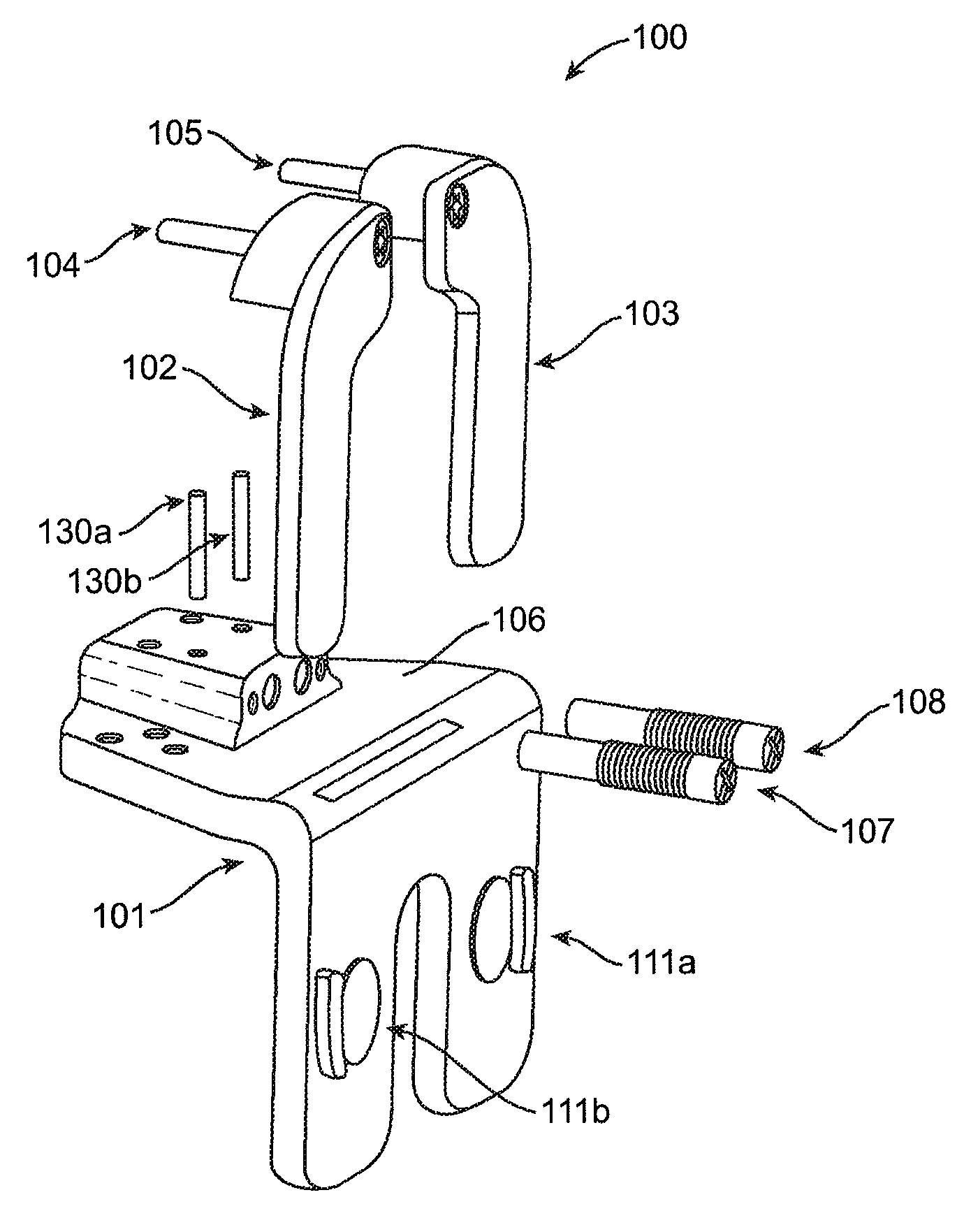
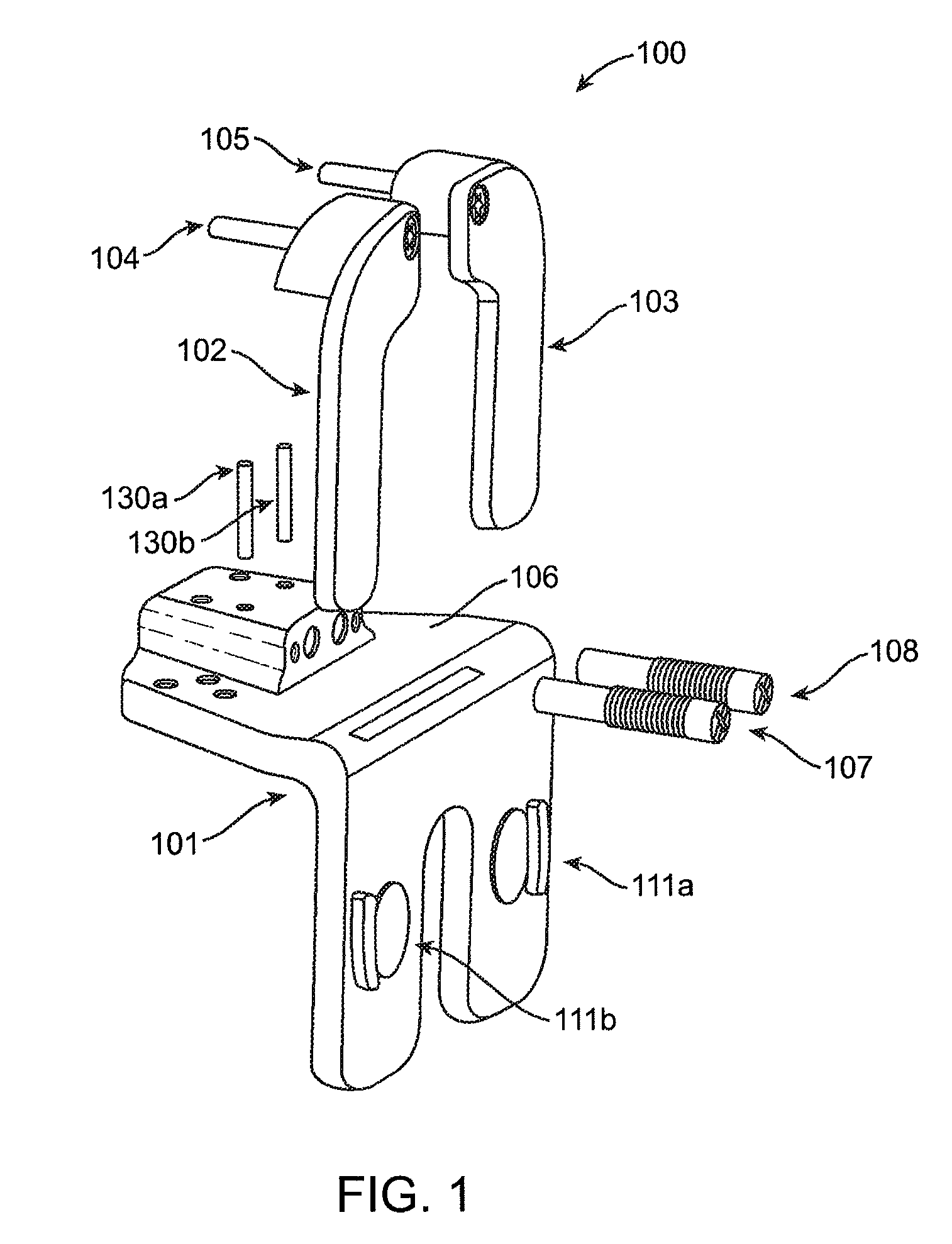
[0077]Referring now to FIG. 1, a distal femoral alignment assembly or component 100 according to embodiments of the invention is shown in an exploded view. As shown in FIG. 1, distal femoral alignment assembly 100 can be used for either the left or right knee, i.e., one side of the distal femoral alignment assembly may be the medial side while the other is the lateral side and vice versa. Distal femoral alignment assembly 100 comprises a main body 101, an adjustable medial femoral portion coupled to the main body, and an adjustable lateral femoral portion coupled to the m...


PUM


Abstract

A system is provided for positioning a cutting guide on a femur of a knee to make a cut along a distal end of the femur during knee surgery. The system may generally include an adjustable femoral attachment member configured to attach to a cut distal end of the femur, a cutting guide removably attachable to the femoral attachment member and configured to guide a surgical saw to make an additional cut on the distal end of the femur, and a force sensor for positioning between the femoral attachment member and a proximal end of a tibia of the knee. The force sensor may include a medial portion for sensing a medial force in the knee and a lateral portion for sensing a lateral force in the knee.

Description

CROSS-REFERENCE TO RELATED APPLICATIONS[0001]The present application is a continuation in part of U.S. patent application Ser. No. 12 / 609,666, filed Oct. 30, 2009, which claims priority to U.S. Provisional Patent Application Ser. No. 61 / 109,770, filed Oct. 30, 2008. The full disclosures of these two applications are incorporated herein by reference.BACKGROUND OF THE INVENTION[0002]1. Field of the Invention[0003]The present invention relates generally to medical surgical devices, systems, and methods. More specifically, the invention relates to devices, systems and methods for facilitating knee surgery procedures, in particular, knee replacement procedures.[0004]2. Description of the Related Art[0005]The knee is generally defined as the point of articulation of the femur with the tibia. Structures that make up the knee include the distal femur, the proximal tibia, the patella, and the soft tissues within and surrounding the knee joint, the soft tissues including the ligaments of the ...

Claims


Application Information

Patent Timeline
Patent Type & Authority Patents(United States)
IPC IPC(8): A61F2/46A61B17/15A61B17/02
CPCA61B17/155A61F2/4657A61B2017/0268A61F2002/4666A61B2090/064A61B17/025
Inventor CHANA, BARJINDER S.FISHER, MICHAEL G.HAIGHT, MICHAELBECKERS, LEOJOHANNABER, KENNETH D
Owner SYNVASIVE TECH
Why Eureka
Try Eureka