Method of determining the position and the speed of a rotor in a synchronous electric machine using state observers

a synchronous electric machine and state observer technology, applied in the field of control of synchronous electric machines, can solve the problems of low-cost position detectors that are not accurate enough, detectors can be subject to failure, and cannot accurately control the torque of electric machines, etc., and achieve accurate position information and robust rejection of measurement noise.

Active Publication Date: 2016-09-13
INST FR DU PETROLE
View PDF17 Cites 2 Cited by
  • Summary
  • Abstract
  • Description
  • Claims
  • Application Information

AI Technical Summary

Benefits of technology

[0012]The present invention is a method of determining the position and the speed of the rotor of the synchronous electric machine, using a state observer for the currents of the electric machine and the injection of signals. The invention provides accurate position information, notably at low speed, without using a position detector. Indeed, signal injection makes the model describing the electric machine's dynamics observable, including at standstill and is robust in rejecting measurement noise.

Problems solved by technology

However, low-cost position detectors are not accurate enough, notably for high rotating speeds, and they therefore do not allow precise control of the torque of the electric machine.
Furthermore, these detectors can be subject to failure or involve measurement noise, thus generating measurement uncertainties.
However, these position detectors have the major drawback of being expensive.
The injection of particular signals involves constraints regarding the electric machine control, which do not enable optimum control of the motor during operation thereof.
But this technique has the drawback of not delivering a precise estimation in a case of near-zero or low motor speed.
However, these hybrid solutions always require using a detector for low electric machine speeds.
Furthermore, the prior art solutions do not have sufficient precision for control of electric machines.
Moreover, some of these Kalman filter observers require many complex calculations.

Method used


Image

  • Method of determining the position and the speed of a rotor in a synchronous electric machine using state observers
  • Method of determining the position and the speed of a rotor in a synchronous electric machine using state observers
  • Method of determining the position and the speed of a rotor in a synchronous electric machine using state observers

Examples


Embodiment Construction

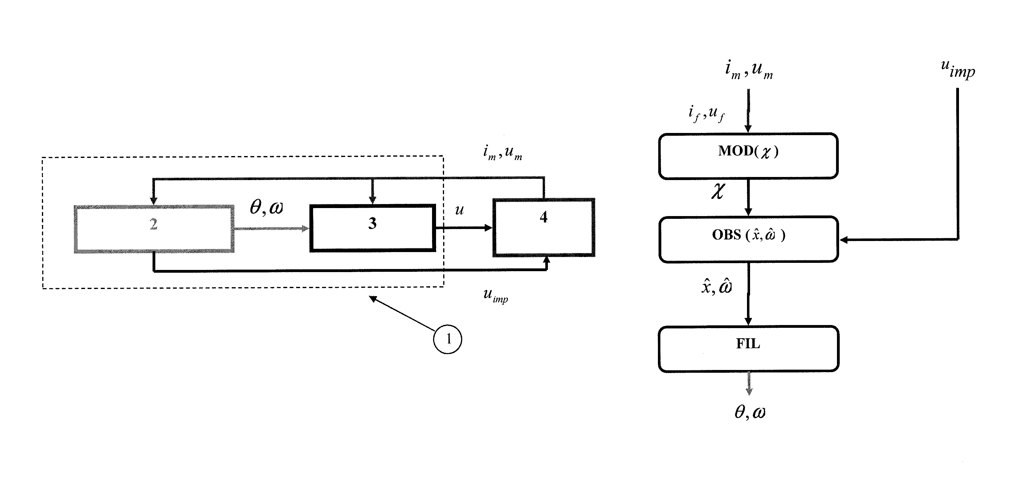
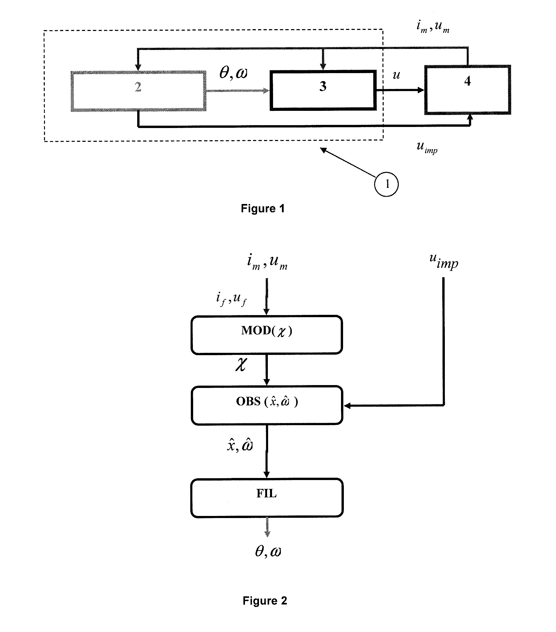
[0046]It is to be noted that the method and the system according to the invention are suited for salient-pole synchronous electric machines. The synchronous electric machine can be either one of using a permanent magnet for providing, controlled excitation or using double excitation. Such a machine is comprised of a rotating part which is the rotor and of a stationary part which is the stator. The rotating part comprises at least one magnet (or electromagnet). The stator comprises at least three coils distributed among three phases, which are supplied electrical current alternately to generate a magnetic field which rotates the rotor. The coils are supported by a frame referred to as the casing.

[0047]FIG. 1 illustrates the control of a synchronous electric machine conventionally made up of three phases. Electric machine (4) is provided with means for measuring the phase voltages and currents; which are well known and not shown. Control means (1) of the electric machine include means...


PUM


Abstract

The invention is a method of determining the position and the speed of the rotor in a synchronous electric machine using a state observer of the currents of the electric machine and the injection of signals. Thus, the invention provides position information which is accurate, notably at low speed, without using a position detector. The invention also is a control method and system for controlling a synchronous electric machine which accounts for the position determined for the rotor.

Description

CROSS REFERENCE TO RELATED APPLICATION[0001]Reference is made to French Patent Application Serial No. 13 / 54.520, filed May 21, 2013, which application is incorporated herein by reference in its entirety.BACKGROUND OF THE INVENTION[0002]1. Field of the Invention[0003]The present invention relates to the control of synchronous electric machines, notably for motor vehicles.[0004]2. Description of the Prior Art[0005]A synchronous machine is comprised of a rotating part which is the rotor and of a stationary part which is the stator. The rotor can be made up of permanent magnets or of a DC-powered coil and a magnetic circuit which is referred to as the electromagnet. The stator comprises three phases with each phase having at least one coil (also referred to as winding) connected thereto with the coils being supplied with electrical power and voltage. An external force is used to rotate the rotor which is a magnetic field induced by an alternating electric current in the coils (windings)...

Claims


Application Information

Patent Timeline
Patent Type & Authority Patents(United States)
IPC IPC(8): G01P3/48G01B7/30H02P23/12
CPCG01B7/30H02P23/12H02P21/18
Inventor DIB, WISSAM
Owner INST FR DU PETROLE
Why Eureka
Try Eureka