Light emitting control knob

a control knob and light-emitting technology, applied in the direction of legends, emergency actuators, electrical appliances, etc., can solve the problems of discoloration of light-blocking layers, user's soon tired of control knobs, and light-emitting control knobs, so as to achieve beautiful design and enhance visibility.

Active Publication Date: 2016-09-13
ASENTEC
View PDF23 Cites 13 Cited by
  • Summary
  • Abstract
  • Description
  • Claims
  • Application Information

AI Technical Summary

Benefits of technology

[0015]In accordance with the light-emitting control knob according to the present invention, the light-blocking layer that forms the light-emitting display windows is not stacked and formed on a top surface of the knob body by way of painting or depositing as in the prior art, but the light-blocking metal plate in which the light-emitting display windows are formed is stacked and formed on a top surface of the knob body. Accordingly, there is an excellent advantage in that a beautiful design can be consistently maintained without a problem, such as discoloration or rubbing-off, despite use of a long period owing to the material characteristics of the metal plate.
[0016]Furthermore, in accordance with the light-emitting control knob according to the present invention, the light diffusion resin layer is stacked on a top surface of the knob body exposed through the light-emitting display windows. Accordingly, there is an excellent advantage in that visibility can be further enhanced because light can be emitted through the light-emitting display windows in a diffused state.
[0017]Furthermore, in accordance with the light-emitting control knob according to the present invention, surface processing unique to metal, such as plating, deposition, anodizing, or hair line processing, is made possible on the light-blocking metal plate. Accordingly, there is an excellent advantage in that a high-class design much more beautiful than a conventional control knob in which a light-blocking layer is stacked and formed on a top surface of the knob body by way of painting or depositing can be provided.

Problems solved by technology

The conventional light-emitting control knob, however, is problematic in that the light-blocking layer is discolored when the control knob is used for a long period or the light-blocking layer is peeled off due to frication with a user's hand because the light-blocking layer is formed and stacked on the top surface of the knob body by way of painting or depositing.
The conventional light-emitting control knob is also problematic in that a user is soon tired of the control knob because the light-blocking layer having a single color is stacked and thus the user's preference to a design part is not satisfied.

Method used


Image

  • Light emitting control knob
  • Light emitting control knob
  • Light emitting control knob

Examples


Embodiment Construction

[0022]Preferred embodiments of the present invention will now be described in detail with reference to the accompanying drawings, but the embodiments are intended to describe the present invention in detail to the extent that those skilled in the art to which the present invention pertains may readily implement the present invention. Accordingly, the embodiments are not intended to limit the technical spirit and category of the present invention.

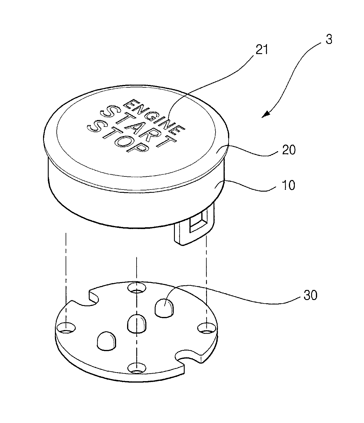
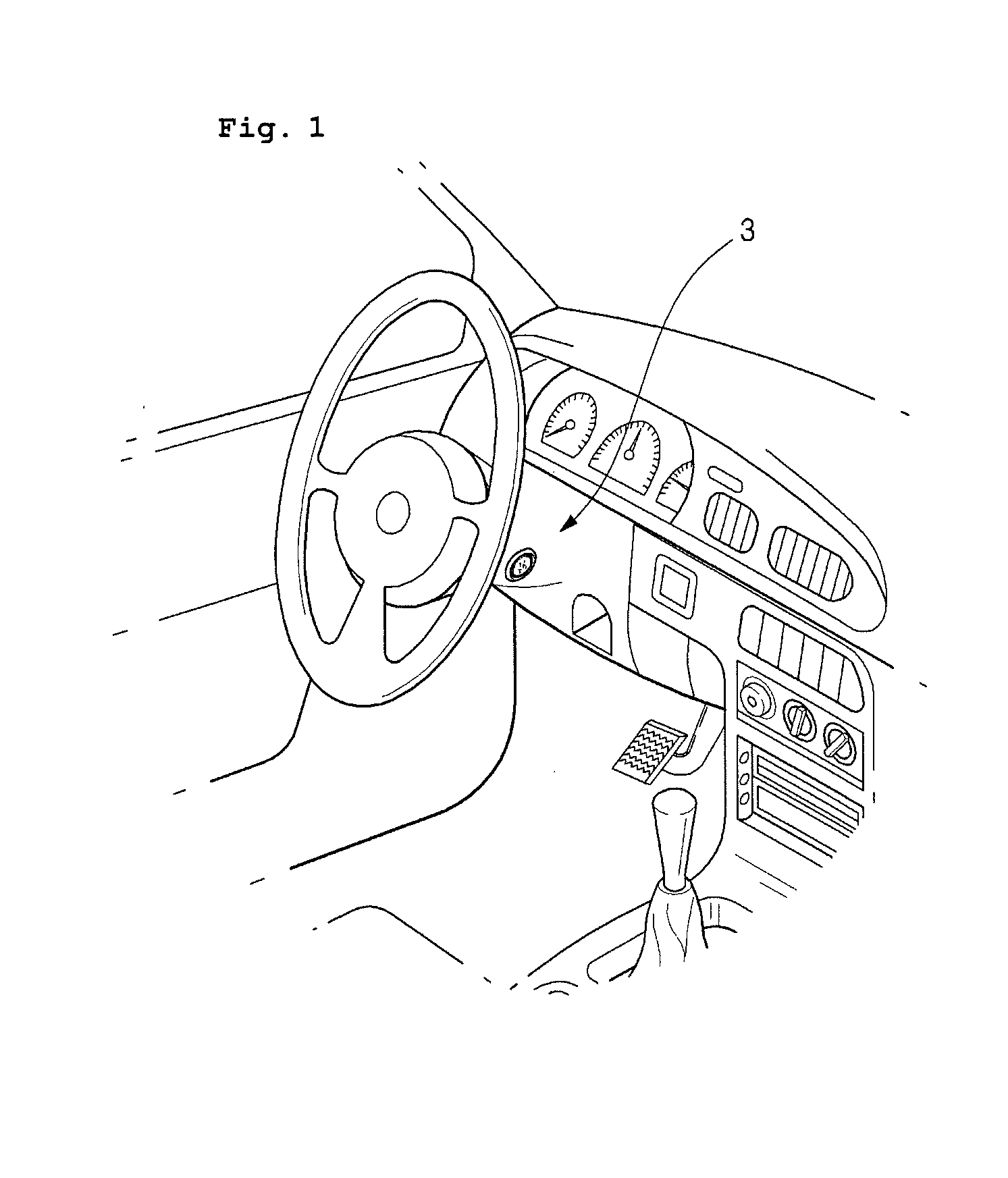
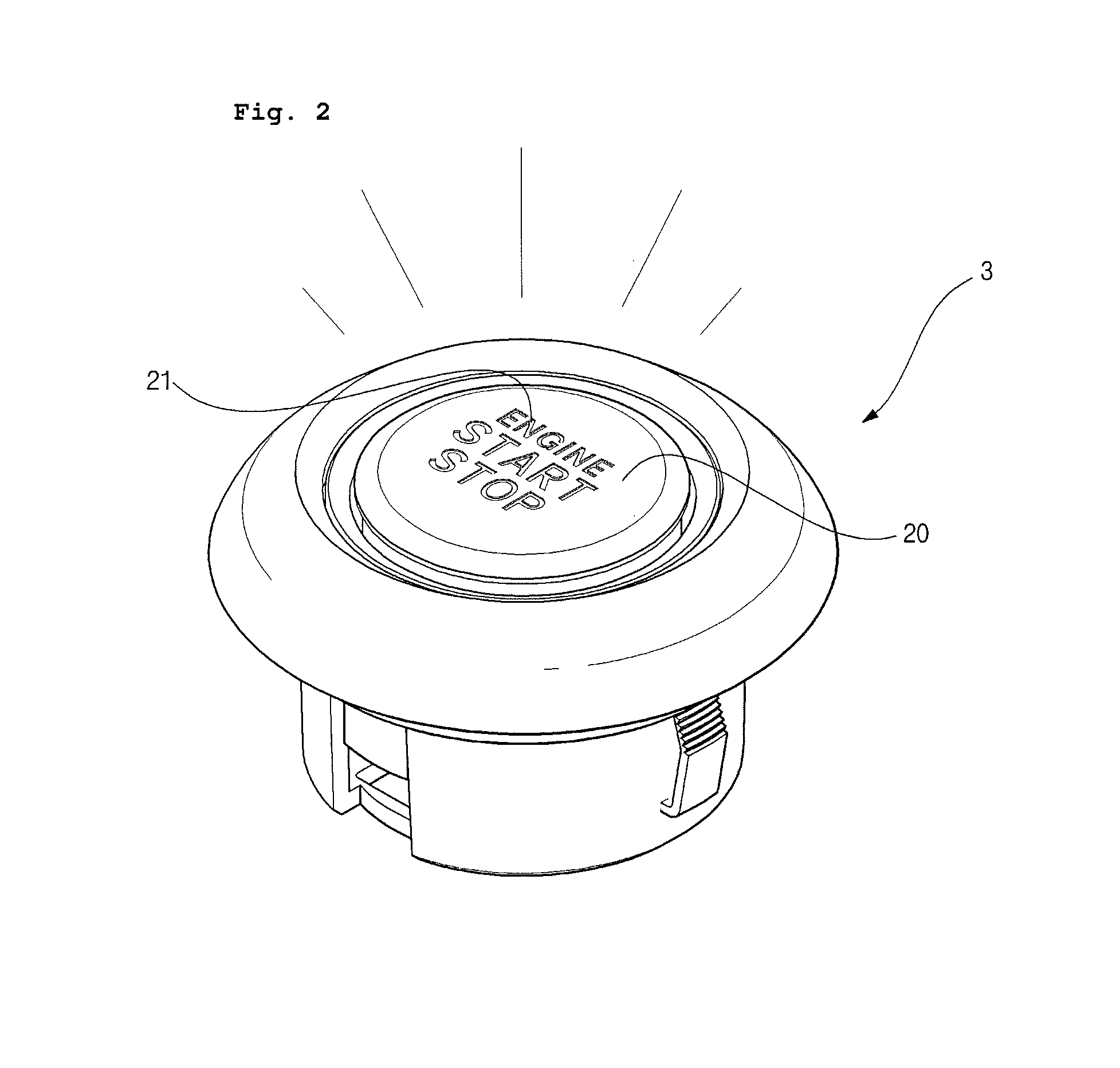
[0023]A light-emitting control knob 1 in accordance with the present invention is applied to a display type control knob, such as a change knob on the transmission gear of a vehicle, a push type control knob, such as the start button 3 of a vehicle, for example, as shown in FIGS. 1 and 2, and a rotation type control knob, such as the volume control dial of audio in vehicles or electronic products in various ways. In particular, the light-emitting control knob increases visibility by externally emitting light, supplied from an underlying ligh...


PUM


Abstract

The present invention provides a light-emitting control knob capable of consistently maintaining a beautiful design without a problem, such as discoloration or rubbing-off, despite use of a long period because a light-blocking metal plate having light-emitting display windows formed therein is stacked and formed on a top surface of a knob body and of providing a much more beautiful and high-class design than a conventional control knob because surface processing unique to metal can be performed on the light-blocking metal plate. The light-emitting control knob in accordance with the present invention includes a knob body made of transparent or semitransparent synthetic resins which transmit light and a light-blocking metal plate formed of a metal plate stacked on a top surface of the knob body and configured to have light-emitting display windows formed therein.

Description

CROSS-REFERENCE TO RELATED APPLICATION[0001]This Application is a Section 371 National Stage Application of International Application No. PCT / KR2012 / 008544, filed Oct. 18, 2012, which claims priority to KR Application No. 10-2012-0068942, filed Jun. 27, 2012, the contents of which are hereby incorporated by reference in their entirety.TECHNICAL FIELD[0002]The present invention relates to a variety of control knobs applied to vehicles or electronic products, and more particularly, to a light-emitting control knob in which a light-blocking metal plate having light-emitting display windows formed therein by, for example, laser processing or CNC processing is stacked and formed on a top surface of a knob body made of synthetic resins, so the light-blocking metal plate is never discolored or rubbed off despite use of a long period, surface processing unique to metal, such as anodizing or hair processing, is made possible, and a high-class design much more beautiful than a conventional co...

Claims


Application Information

Patent Timeline
Patent Type & Authority Patents(United States)
IPC IPC(8): H01H19/02H01H19/14H01H13/02H01H13/14
CPCH01H13/14H01H19/14H01H19/025H01H13/023H01H2219/014H01H2219/028H01H2219/036H01H2219/039H01H2221/07H01H2229/048H01H2229/056H01H9/18
Inventor NA, SUN-HE
Owner ASENTEC
Why Eureka
Try Eureka