
Computer controlled laser therapy treatment table

a laser therapy and computer controlled technology, applied in the field of therapy tables, can solve the problems of not being able to provide the versatility and comfort level of chiropractic patients, not being able to support newer treatment techniques, etc., and achieve the effects of improving padding, facilitating patient movement, and facilitating patient movemen

Active Publication Date: 2016-09-20
JAGGER MARK
View PDF57 Cites 6 Cited by
  • Summary
  • Abstract
  • Description
  • Claims
  • Application Information

AI Technical Summary

Benefits of technology

The invention is a multi-function adjustable chiropractic table with several attachments. It includes a cervical section head support for improved comfort and a three-point head strap for securely securing a patient's head. The table also has casters that can move and retract for stable support. Additionally, there is a traction platform for decompression therapy and a laser enhanced spinal decompression apparatus for unassisted treatments. These attachments make the table more versatile and comfortable for patients and provide improved treatment results.

Problems solved by technology

Therefore, treatment tables have been utilized for some time in these practices, with a typical example of such a chiropractic tables generally being illustrated within FIG. 1 of U.S. Pat. No. 7,472,441 to Steffenmeier for “Automatic Tilt-Elevating Chiropractic Table.” However, despite the patentable and other advances that have been made to date, they have not developed sufficiently to support newer treatment techniques or to be able to provide the versatility and comfort level that is expected and needed by chiropractic patients.

Method used


Image

  • Computer controlled laser therapy treatment table
  • Computer controlled laser therapy treatment table
  • Computer controlled laser therapy treatment table

Examples


Embodiment Construction

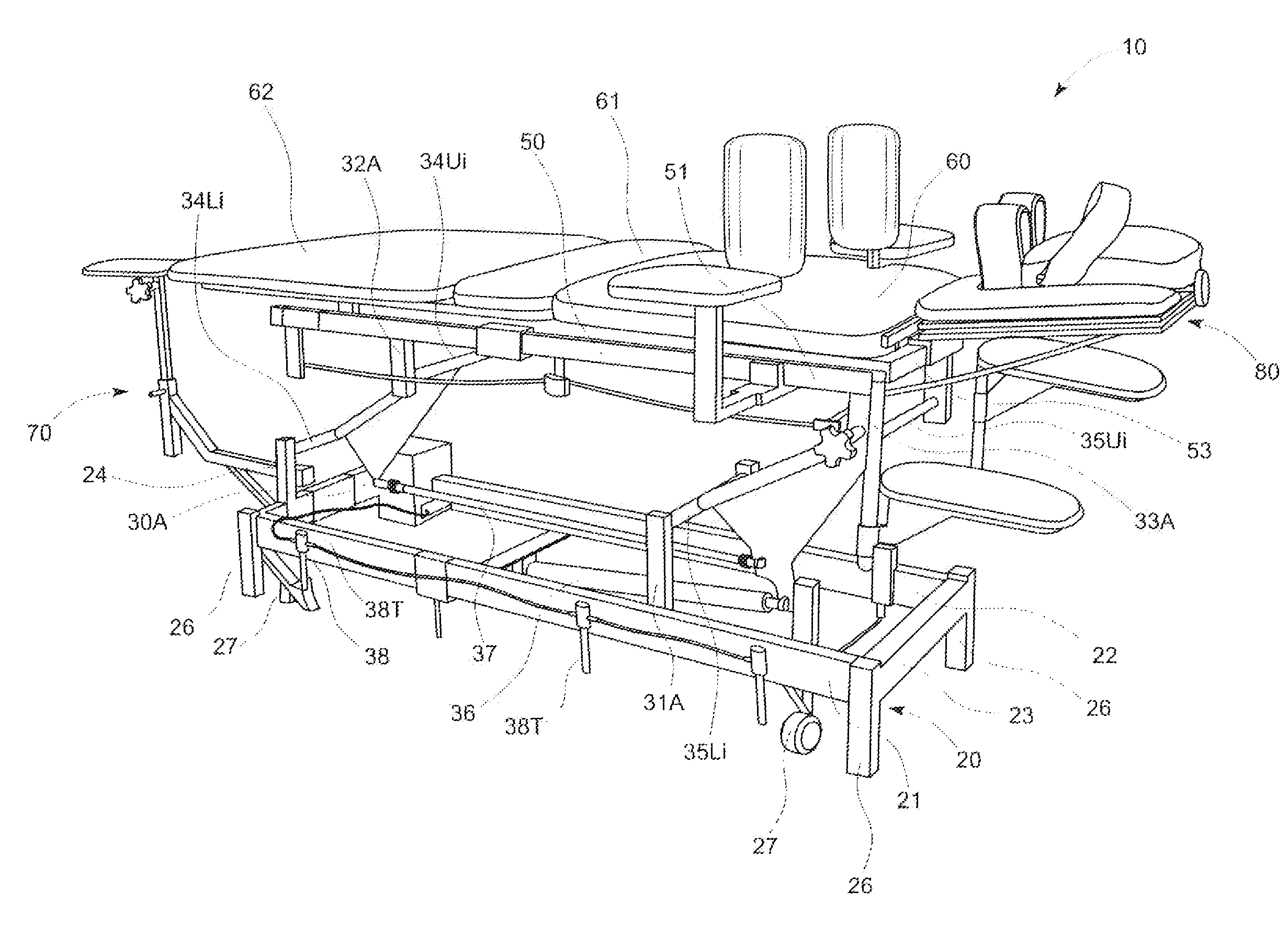
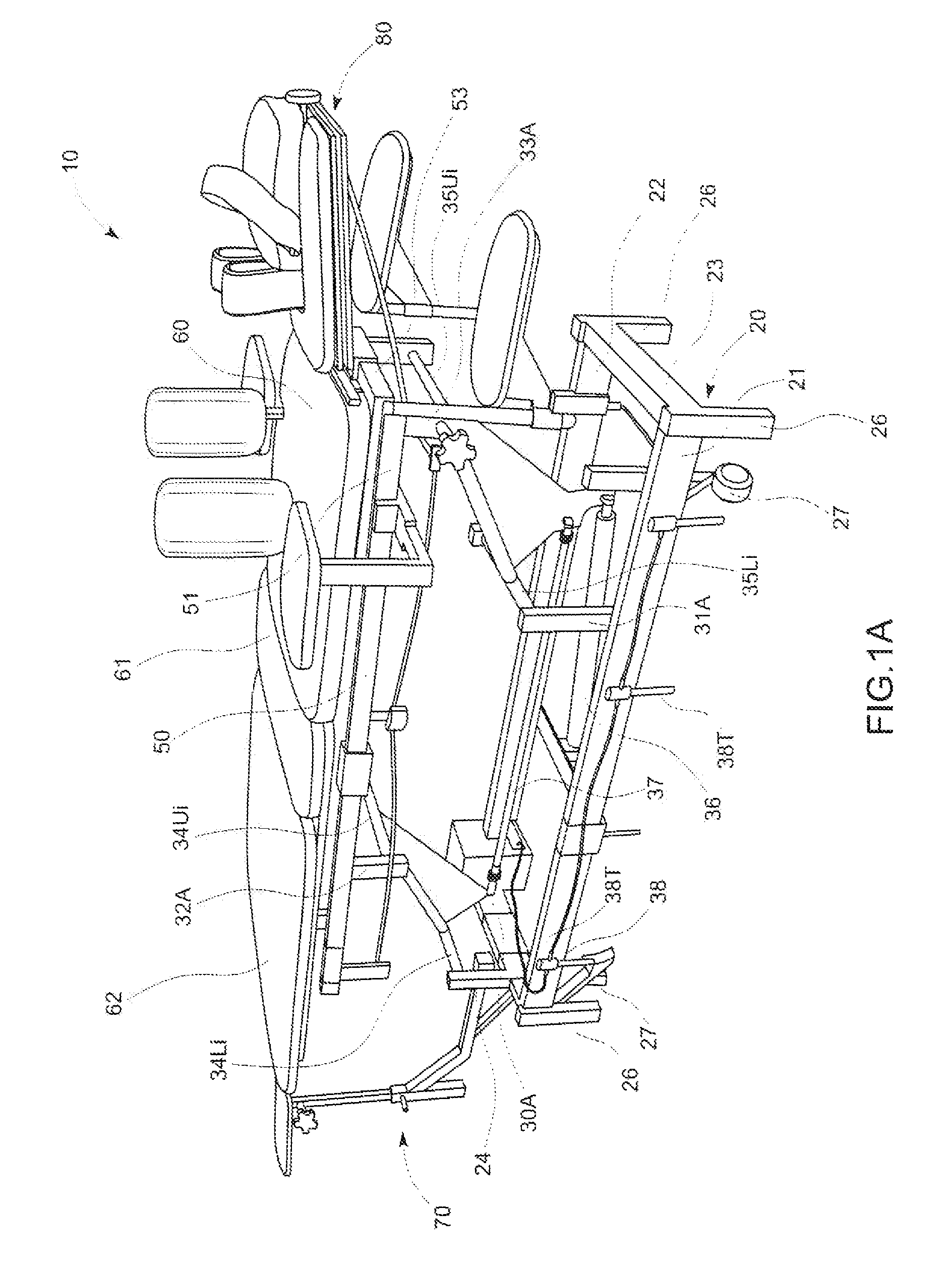
[0077]FIG. 1 shows a first embodiment of the multi-function adjustable treatment table assembly 10 of the present invention. The table may comprise a base (support) frame 20 which may be made of a single unitary piece, perhaps being a machined part or a cast part, and potentially forming a race-track shape. In general, the base frame 20 may form at least a first elongated side 21 and a second elongated side 22, which may be connected by a first cross-member 23 and a second cross-member 24. Where four separate elongated sides 21 and 22, and separate cross-members 23 and 24 are utilized, they may be secured together using any suitable mechanical fasteners, or they may be welded together.

[0078]Extending downward from the base frame 20 may be four support legs 26 being fixed to the frame, and preferably spaced about the frame to provide stable support. In one embodiment, the legs 26 may be at a location proximal to the joining of the sides 21 and 22, and cross-members 23 and 24. The mul...


PUM


Abstract

A multi-function, adjustable chiropractic table comprises a body section fixed to a table frame. A cervical section is pivotally attached to the table frame and securable at a desired angle. The cervical section comprises a padded head support, forehead strap, and neck bolsters. The head support is slidably mounted in a tray and translatable therein using a scissors mechanism, for linear axial traction. Pivotally mounting the tray to the cervical section permits lateral traction. A four-bar linkage, including a base frame, permits raising / lowering of the table using an actuator activated by a foot triggered wave switch comprising proximity sensors. The body section comprises a chest, lumbar, and leg sections. The chest section is replaceable with a treatment module comprising hot and cold compresses, or a laser enhanced spinal decompression therapy apparatus comprising a laser driven by two linear actuators to emit light according to one or more treatment protocols.

Description

CROSS REFERENCES TO RELATED APPLICATIONS[0001]This application claims priority on U.S. Provisional Application Ser. No. 61 / 465,200, filed on Mar. 15, 2011, titled “Innovations to Multi-Functional Medical / Rehabilitation Treatment Tables, Protocols and Associated Equipment,” and is a continuation of U.S. Application Ser. No. 13 / 236,465, titled “Improved Multi-Function Medical / Rehabilitation Treatment Table and Equipment,” filed on Sep. 19, 2011now abandoned, with the disclosures of each incorporated herein by reference.FIELD OF THE INVENTION[0002]The present invention relates to the field of therapy tables, and more particularly to apparatus which are capable of providing increased performance capability for a medical practitioner while reducing the therapist's workload.BACKGROUND OF THE INVENTION[0003]Treatment tables are commonly used in various different medical fields, including the manual-therapy professions, such massage therapy, osteopathy, and physical therapy, and also for ch...

Claims


Application Information

Patent Timeline
Patent Type & Authority Patents(United States)
IPC IPC(8): A61N5/067A61H1/00A61N5/06A61H1/02A61G13/00A61G13/08A61B18/20A61G13/12
CPCA61N5/0613A61H1/0222A61B2018/2085A61G13/009A61G13/08A61G13/121A61G2203/34A61G2203/36A61G2203/40A61H1/0296A61H2201/1607A61H2201/1664A61H2201/1676A61N2005/067A61N2005/0632A61N2005/0644A61B2018/20351A61B2018/20355A61B2018/20361A61N5/067
Inventor JAGGER, MARK
Owner JAGGER MARK
Learn More