
Apparatus and method for synchronized multi-stage electromagnetic rivet guns

a multi-stage, electromagnetic technology, applied in the field of apparatus and method for synchronized multi-stage electromagnetic rivet guns, can solve the problems of high cost, high cost, and high cost, and achieve the effect of reducing the cost of synchronization and maintenance, and avoiding the need for synchronization and maintenan

Active Publication Date: 2016-09-20
THE BOEING CO
View PDF9 Cites 6 Cited by
  • Summary
  • Abstract
  • Description
  • Claims
  • Application Information

AI Technical Summary

Problems solved by technology

Further, the impact energy of the rivet gun is typically designed to completely form the button end on the tail of the rivet and cause the desired degree of interference between the rivet shank and the hole, and / or between the rivet head and the surface of the structure.
However, the typical rivet-installation process has a number of drawbacks.
In practice it is extremely difficult to precisely control the propagation of the impact energy throughout the system.
The lack of control over the propagation of the impact energy throughout the system may lead to a rivet that fails to meet the desired degree of interference.
Much of this impact energy is transferred to the rivet thereby leading to the deformation of the rivet.
Since it is difficult to precisely control the propagation of this impact energy, an undesired amount of energy may be transferred to the structure and / or the rivet.
Thus, the traditional rivet-installation process often results in rivets that fail to precisely meet a desired degree of interference.
Another drawback of the traditional rivet-installation process is that the typical rivet installation process involves a large amount of human feedback.
Yet another drawback of the traditional rivet-installation process is that the typical rivet installation process is unsuitable for joining structures such as composite materials.
However, currently it is extremely difficult to use rivets to join composite materials, due to the forces that the traditional rivet process imparts on the composite material.
Since composite materials typically cannot sustain the forces of the standard rivet-installation process, rivets are not commonly used to join composite materials.

Method used


Image

  • Apparatus and method for synchronized multi-stage electromagnetic rivet guns
  • Apparatus and method for synchronized multi-stage electromagnetic rivet guns
  • Apparatus and method for synchronized multi-stage electromagnetic rivet guns

Examples


Embodiment Construction

[0022]In the following detailed description, reference is made to the accompanying drawings, which form a part hereof. In the drawings, similar symbols typically identify similar components, unless context dictates otherwise. The illustrative embodiments described in the detailed description, drawings, and claims are not meant to be limiting. Other embodiments may be utilized, and other changes may be made, without departing from the spirit or scope of the subject matter presented herein. It will be readily understood that the aspects of the present disclosure, as generally described herein, and illustrated in the figures, can be arranged, substituted, combined, separated, and designed in a wide variety of different configurations, all of which are explicitly contemplated herein.

1. Overview of Example Methods and Systems

[0023]As mentioned above, a traditional rivet-installation process has a number of drawbacks. For instance, the typical rivet-installation process creates impact ene...


PUM

PropertyMeasurementUnit
timeaaaaaaaaaa
timeaaaaaaaaaa
timeaaaaaaaaaa

Abstract

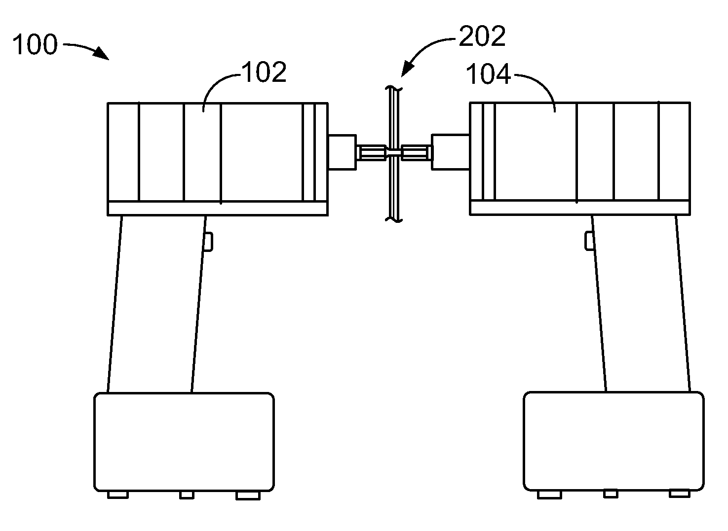
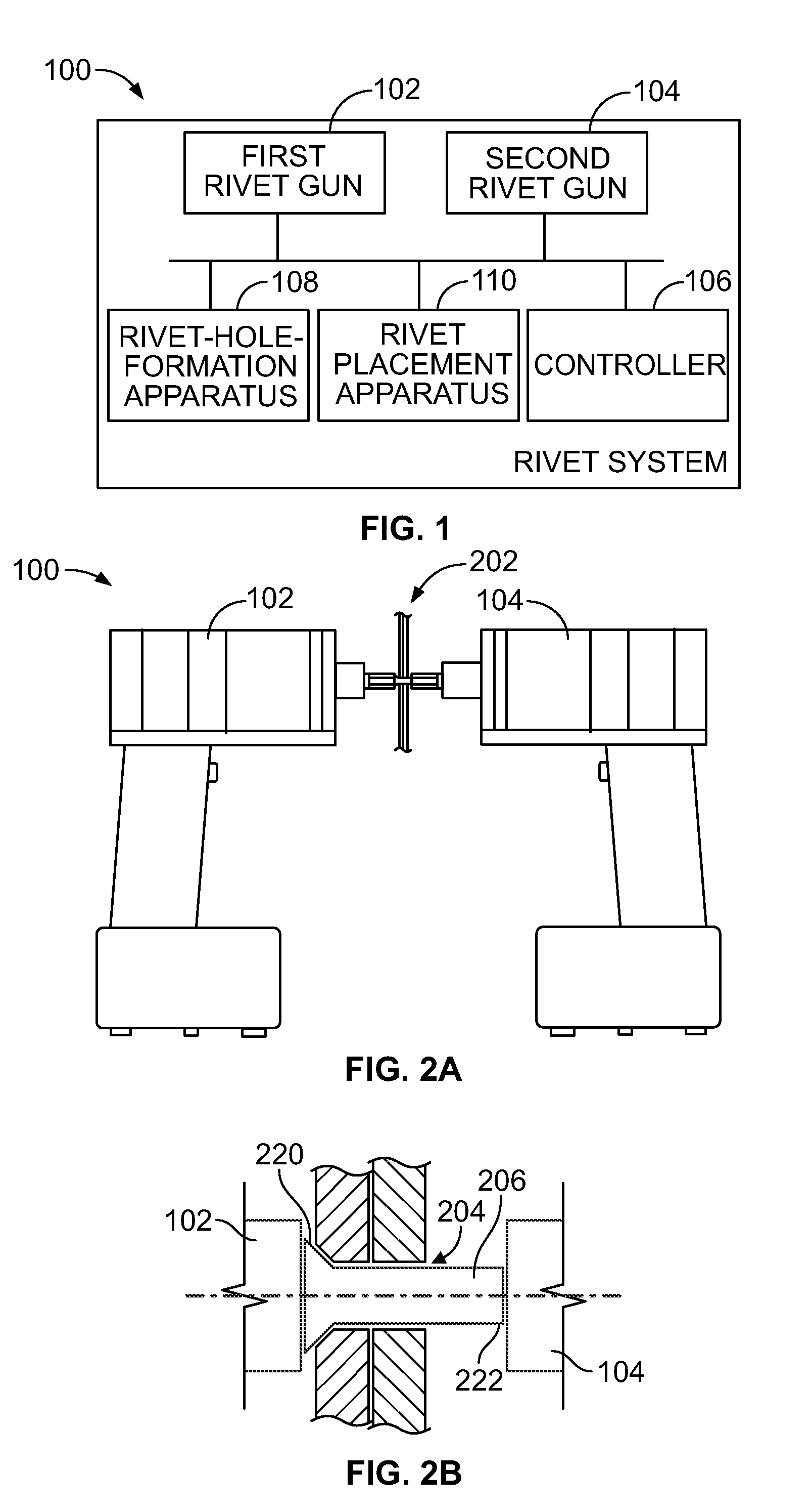
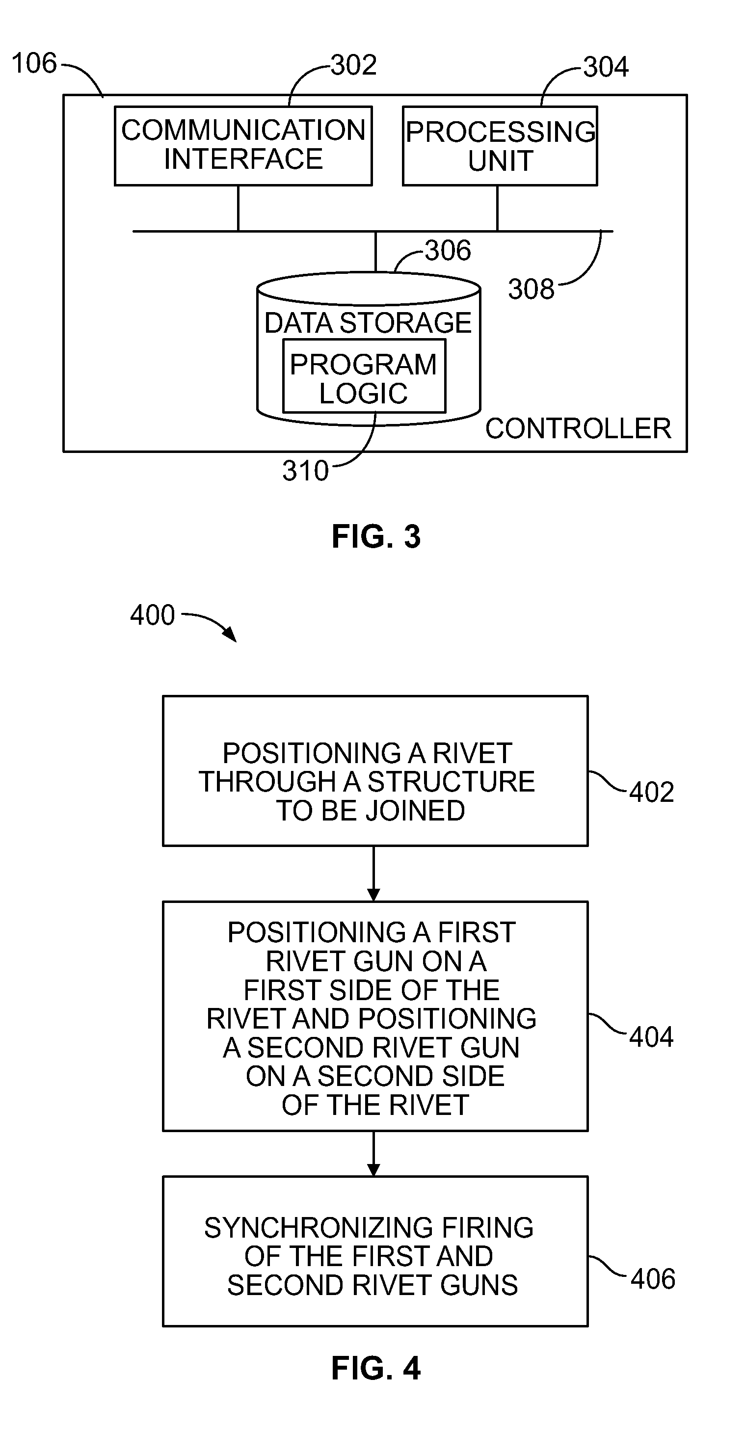
A method and system for installing rivets is disclosed. The method involves positioning a rivet through a structure to be joined. The method further involves positioning a first rivet gun on a first side of the rivet and positioning a second rivet gun on a second side of the rivet. The method also involves synchronizing firing of the first and second rivet guns, so as to cancel forces that otherwise would propagate into the structure during installation of the rivet.

Description

BACKGROUND[0001]Unless otherwise indicated herein, the materials described in this section are not prior art to the claims and are not admitted to be prior art by inclusion in this section.[0002]In the aerospace industry, structural fasteners such as rivets are commonly used to join a structure such as metal sheet components. In an example, rivets are used for construction of primary structures of aircraft (e.g., fuselage, wings, and tail), as well as secondary structures (e.g., rudders). Rivets commonly are used for fastening an aerodynamic skin to a frame to provide a strong aerodynamically smooth surface. Further, rivets are also commonly used in the interior structure of aircrafts since rivets provide a light and secure method of fastening structural components together.[0003]Before being installed, a rivet typically consists of a cylindrical shaft with a head on one end and a tail on the other end (commonly referred to as the buck-tail). The installation process for installing ...

Claims


Application Information

Patent Timeline
Patent Type & Authority Patents(United States)
IPC IPC(8): B21J15/28B21J15/24B21J15/04B21J15/02
CPCB21J15/28B21J15/02B21J15/04B21J15/24Y10T29/4976Y10T29/4995Y10T29/49769Y10T29/49776Y10T29/49833Y10T29/49943Y10T29/49945Y10T29/5303Y10T29/53039Y10T29/53052Y10T29/53065Y10T29/5377B21J15/142B21J15/32B21J15/38
Inventor CHRISTENSEN, TYLERSARH, BRANKOGROSSNICKLE, JAMES A.
Owner THE BOEING CO
Learn More