
Electronic device and hinge assembly

a technology of electronic devices and hinges, applied in the field of hinges, can solve the problems of large manpower and operating costs, damage to the internal flexible circuit board or bus line, and the collapse of the display device face panel or outer cover, etc., and achieve the effect of stabilization

Active Publication Date: 2016-09-20
DATAVAN INT
View PDF4 Cites 14 Cited by
  • Summary
  • Abstract
  • Description
  • Claims
  • Application Information

AI Technical Summary

Benefits of technology

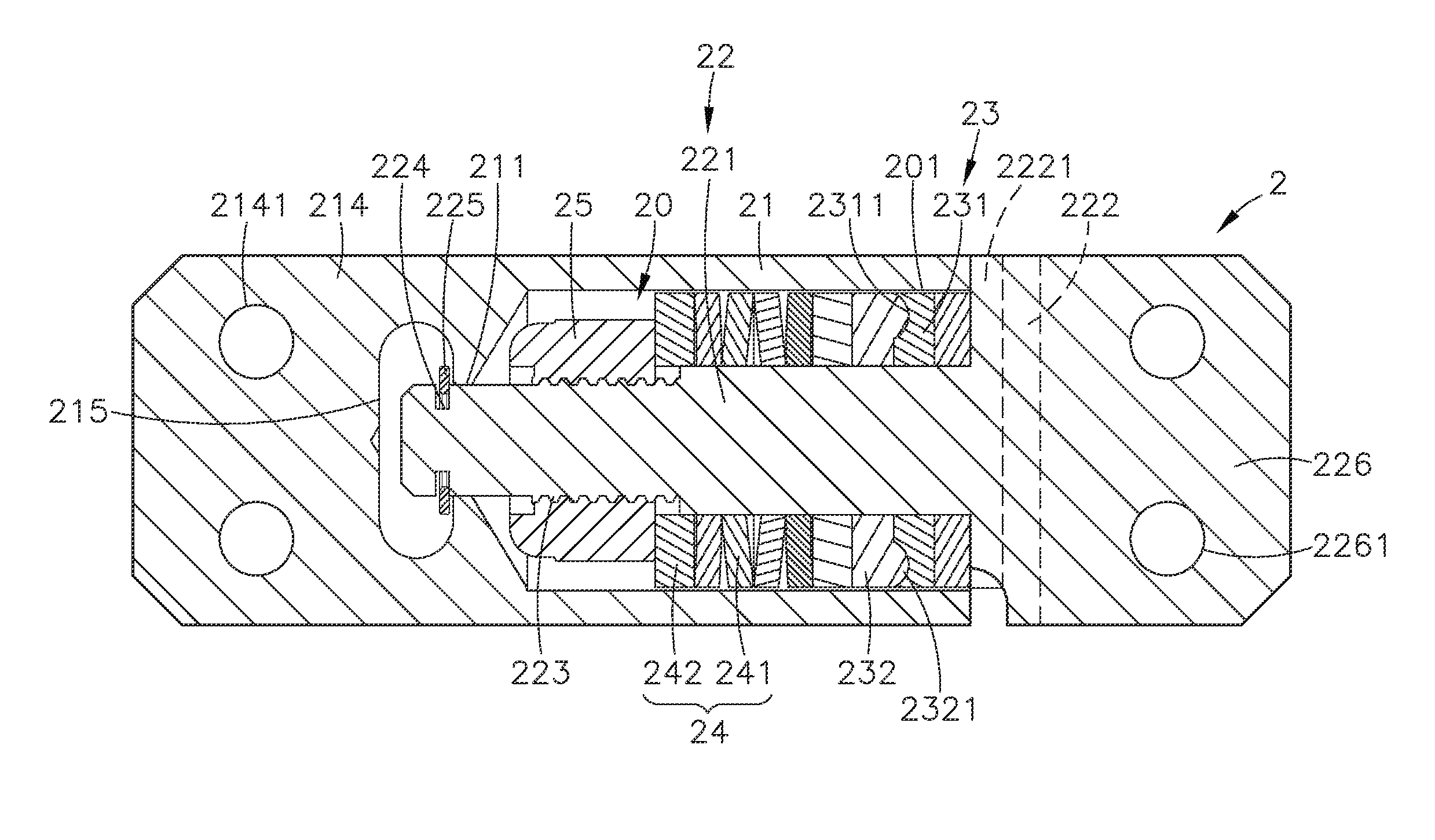
The present invention provides an electronic device and hinge assembly, which allows adjustment of the angular position of the main unit relative to the base through a series of angles. Each hinge device comprises a casing, a pivot shaft, and a friction wheel set and damper mounted on the pivot shaft. The friction wheel set comprises a first friction wheel and a second friction wheel, and each raised portion of the second friction wheel engages into the recessed portions of the first friction wheel. After each raised portion moved away from one recessed portion and reached to a respective next recessed portion, elastic members of the damper release elastic potential energy to hold down the raised portions of the second friction wheel. Thus, the hinge devices allow adjustment of the angular position of the main unit relative to the base smoothly and stably. The invention enhances angular adjustment smoothness and stability.

Problems solved by technology

Many retail operators adopt point of sales management system (POS), electronic ordering system (EOS) or computer assisted ordering system for registering and calculating transactions, scanning barcodes, drawing up invoices or receipts, ordering, providing the latest news, analyzing and handling product information, membership information and sales data, saving a large amount of manpower and operating costs.
However, a user may apply excessive force to turn the display device, face panel or outer cover relative to the mainframe or base over the limited range of angles, leading to internal flexible circuit board or bus line damage.
Further, if the user closes the display device face panel or outer cover on the mainframe or base in a rush, the display device face panel or outer cover can be crushed.
There are improved designs of hinge devices capable of providing high torque, however, these improved designs of hinge devices commonly have a complicated structure, and their fabrication requires high precision.
Thus, these improved designs of hinge devices are not suitable for mass fabrication, and their manufacturing cost is inevitably high.

Method used


Image

  • Electronic device and hinge assembly
  • Electronic device and hinge assembly
  • Electronic device and hinge assembly

Examples


Embodiment Construction

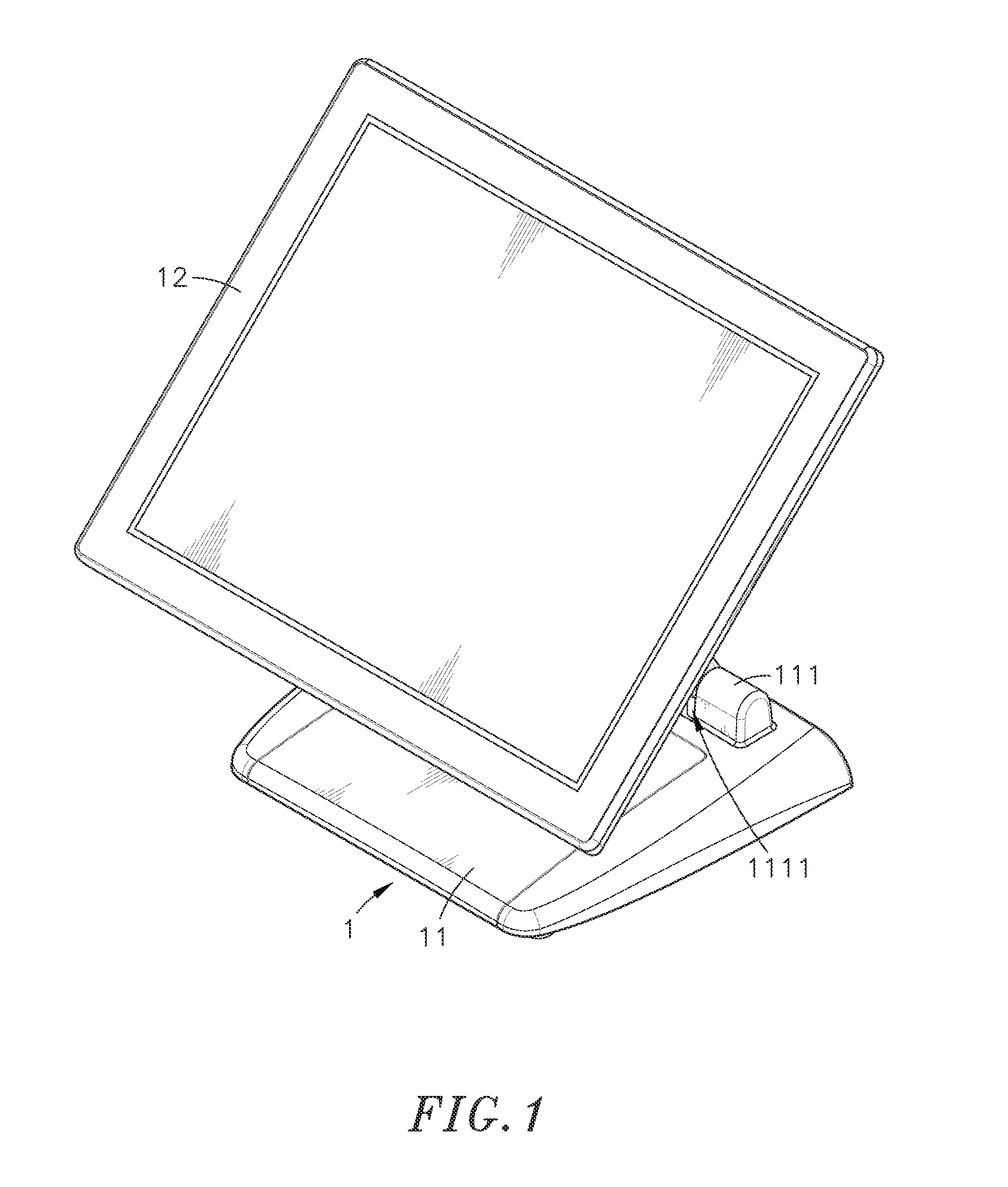
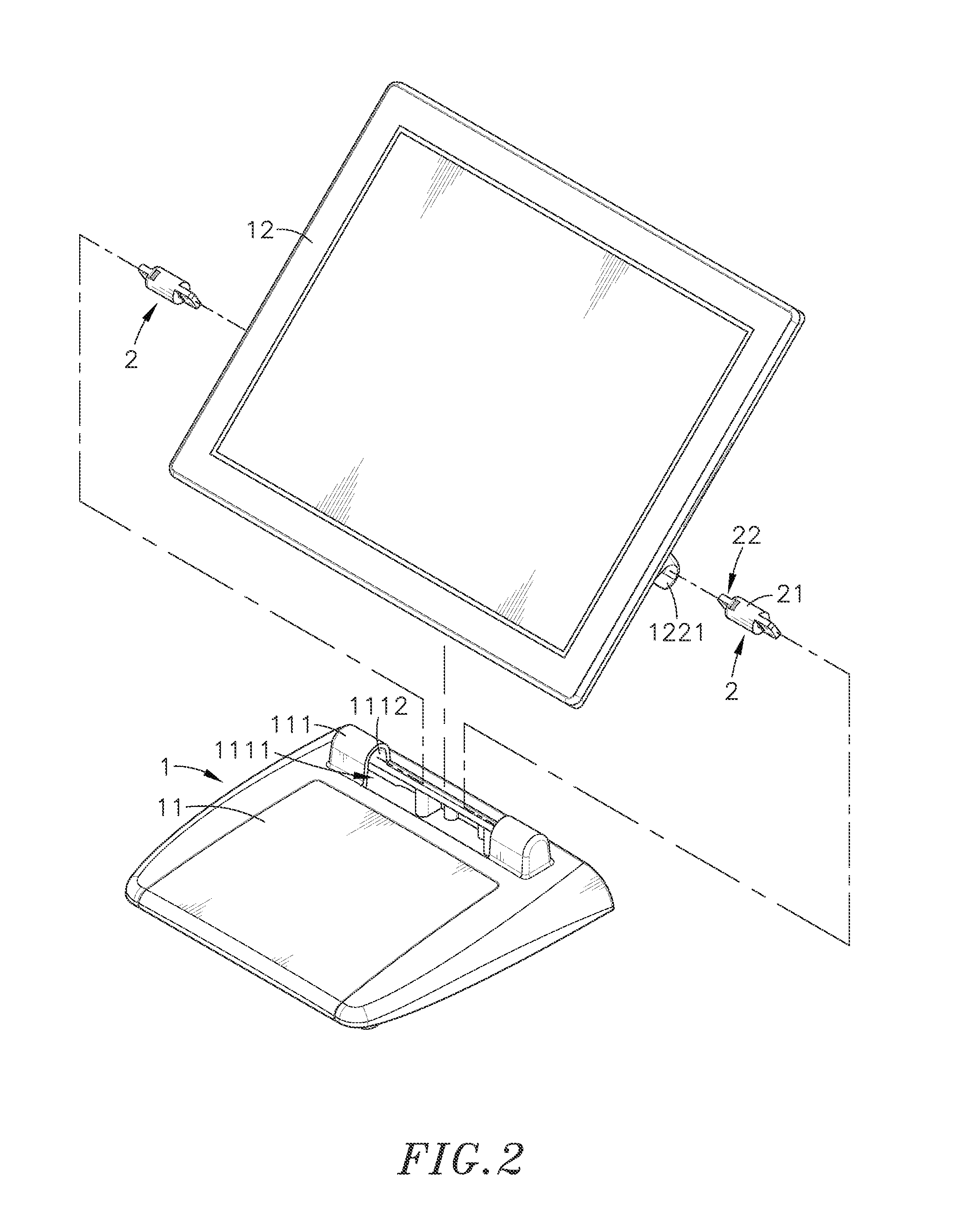
[0017]Referring to FIGS. 1-6, an oblique top elevational view of an electronic device and hinge assembly in accordance with the present invention, an exploded view of the electronic device and hinge assembly, another exploded view of the electronic device and hinge assembly, a sectional side view of the hinge of the electronic device and hinge assembly, a schematic enlarged view of a part of the electronic device and hinge assembly and an adjusted side view of the electronic device and hinge assembly are shown. The electronic device and hinge assembly comprises an electronic device body 1, and a plurality of hinge devices 2.

[0018]The electronic device body 1 comprises a base 11, a main unit 12, and a support arm 122 pivotally coupled between the base 11 and the main unit 12 by the hinge devices 2. The base 11 comprises a first pivot-connection block 111 raised from a top wall thereof. The first pivot-connection block 111 comprises a first shaft groove 1111 extending along the length...


PUM


Abstract

An electronic device and hinge assembly includes an electronic device body including a base and a main unit, and hinge devices pivotally connecting the base and the main unit for allowing adjustment of the angular position of the main unit relative to the base step by step in a series of angles. Each hinge device includes a casing affixed to one of the base and the main unit, a pivot shaft connected to the base and the main unit and rotatably inserted through the casing and secured by a retaining ring, and a friction wheel set and a damper mounted on the pivot shaft. The friction wheel set includes a first friction wheel and having recessed portions equiangularly spaced at one side thereof, and a second friction wheel rotatable with the pivot shaft relative to the first friction wheel and having raised portions respectively engageable into the recessed portions.

Description

BACKGROUND OF THE INVENTION[0001]1. Field of the Invention[0002]The present invention relates to hinge technology, and more particularly to an electronic device and hinge assembly, which includes an electronic device body including a base and a main unit, and hinge devices to pivotally connect the base and main unit of the electronic device body, wherein each hinge device consists of a pivot shaft, a friction wheel set and a damper for allowing adjustment of the angular position of the main unit relative to the base smoothly and stably through a series of angles.[0003]2. Description of the Related Art[0004]Following fast development of electronic technology, advanced electronic apparatus having the characteristics of strong operational capabilities, high operating speed and small size have been continuously created. With the popularity of computers and networks, most general family or company will use computers and the Internet. Even in the shops, restaurants and other places, we ca...

Claims


Application Information

Patent Timeline
Patent Type & Authority Patents(United States)
IPC IPC(8): G06F1/16E05D11/08E05F5/02E05D11/00E05D3/12
CPCG06F1/16E05D3/12E05D11/0054E05D11/082E05F5/02G06F1/1601G06F1/181G06F2200/1612G06F2200/1631
Inventor LEE, CHUN-YICHANG, YU-CHEN
Owner DATAVAN INT
Learn More