
Method for manufacturing coke

a blast furnace coke and coke technology, applied in the direction of instruments, fuels, material analysis, etc., can solve the problems of difficult fluidity determination, increased cost, and inconvenient determination of value, so as to increase the freedom of purchasing materials, increase the coke strength, and increase the material cost

Active Publication Date: 2016-10-11
JFE STEEL CORP
View PDF6 Cites 20 Cited by
  • Summary
  • Abstract
  • Description
  • Claims
  • Application Information

AI Technical Summary

Benefits of technology

[0018]The present invention has been completed in order to solve the problems described above, and the present invention aims to provide a method for manufacturing coke by which it is possible to increase coke strength while preventing an increase in the material cost of raw coal.
[0042](b) In addition, since there is an increase in parameters of coal properties which causes an increase in the freedom of purchasing materials, it is possible to increase coke strength without increasing material cost.
[0043](c) Moreover, since the method according to the present invention can be applied to non- or slightly-caking coal whose fluidity is too low to evaluate using a Gieseler plastometer, it is possible to significantly increase the freedom of blending raw coal.

Problems solved by technology

Since this kind of coal is expensive, there is a problem of an increase in cost.
In addition, in the case where non- or slightly-caking coal which is poor in fluidity is used, since there is a decrease in detection sensitivity for an index indicating fluidity, it is difficult to determine fluidity and there is a problem in that the determined value is not useful.
In addition, since the method described in (B) focuses on the fluidity and viscosity of coal which are indices having improved detection sensitivity for maximum fluidity (MF) in a practical sense, there is a problem regarding cost as is the case with the method described in (A).
In addition, an apparatus to be used in the method described in (B) is expensive, special, and inconvenient.
However, since a parameter of a conventional coke strength equation is used in this method, this method is still not superior to conventional methods, which results in the problem regarding cost being left to be solved.
In addition, although the interaction among coal particles is estimated in this method, since it is not an estimation based on a physical property regarding the adhesiveness of coal particles, the prediction precision of strength is not sufficiently good and there is a problem in that there is inconvenience in the case where a blending effect coefficient is obtained by practical measurement.

Method used


Image

  • Method for manufacturing coke
  • Method for manufacturing coke
  • Method for manufacturing coke

Examples


example 1

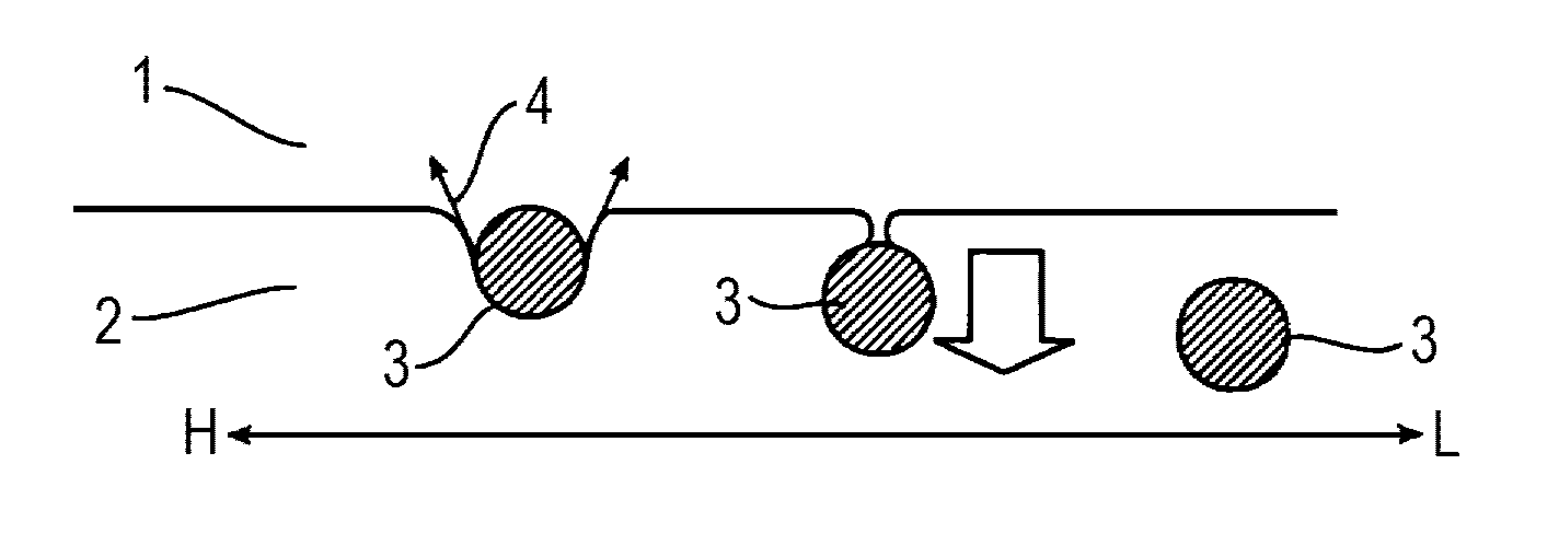
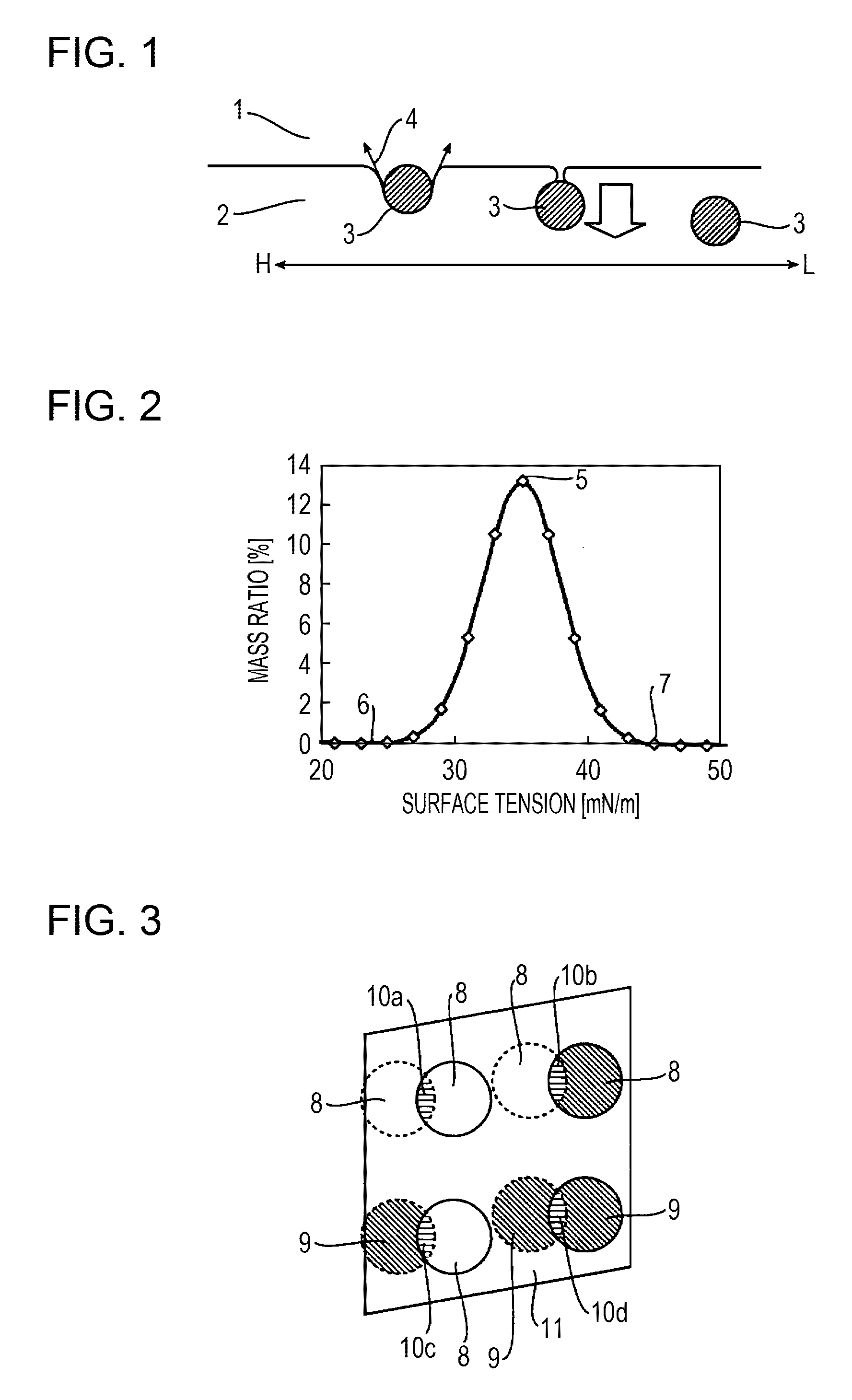
[0097]An example case where high strength coke was manufactured on the basis of interfacial tension will be described. In order to clarify the conditions for manufacturing high strength coke without depending on conventional parameters of coal properties, an experiment was carried out under the condition that conventional parameters of coal properties were constant. Thirteen kinds of coal (the kinds of coal A through M) were prepared, and, first, tests for the properties of these kinds of coal were carried out in order to determine mean maximum reflectance of vitrinite (Ro), Gieseler maximum fluidity (log MF), and surface tension derived by a film flotation method, which are conventional parameters of coal properties. Mean maximum reflectance was determined in accordance with JIS M 8816 (mean maximum reflectance of vitrinite of coal), and Gieseler maximum fluidity was determined in accordance with JIS M 8801. The measurement of surface tension by a film floatation method was carried...

example 2

[0103]An example case where high strength coke was manufactured by controlling interfacial tension under the condition that the blending ratio of coal having a low MF is high. Eight kinds of coal were prepared, and, first, tests for coal properties using these kinds of coal were carried out. The measurement items were Ro (mean maximum reflectance), log MF, and surface tension as is the case with [EXAMPLE 1] described above. The measurement methods were also the same as those in [EXAMPLE 1]. The average value of surface tension distribution was derived from the determined surface tension distribution using equation (10), and this average value of surface tension distribution was used as an index of surface tension (γ). Using the results of the tests for coal properties, 5 classes of blend (blends E through I) having different interfacial tensions were determined. In order to eliminate the influences of other parameters on coke strength, the blending ratios of all the kinds of coal we...

example 3

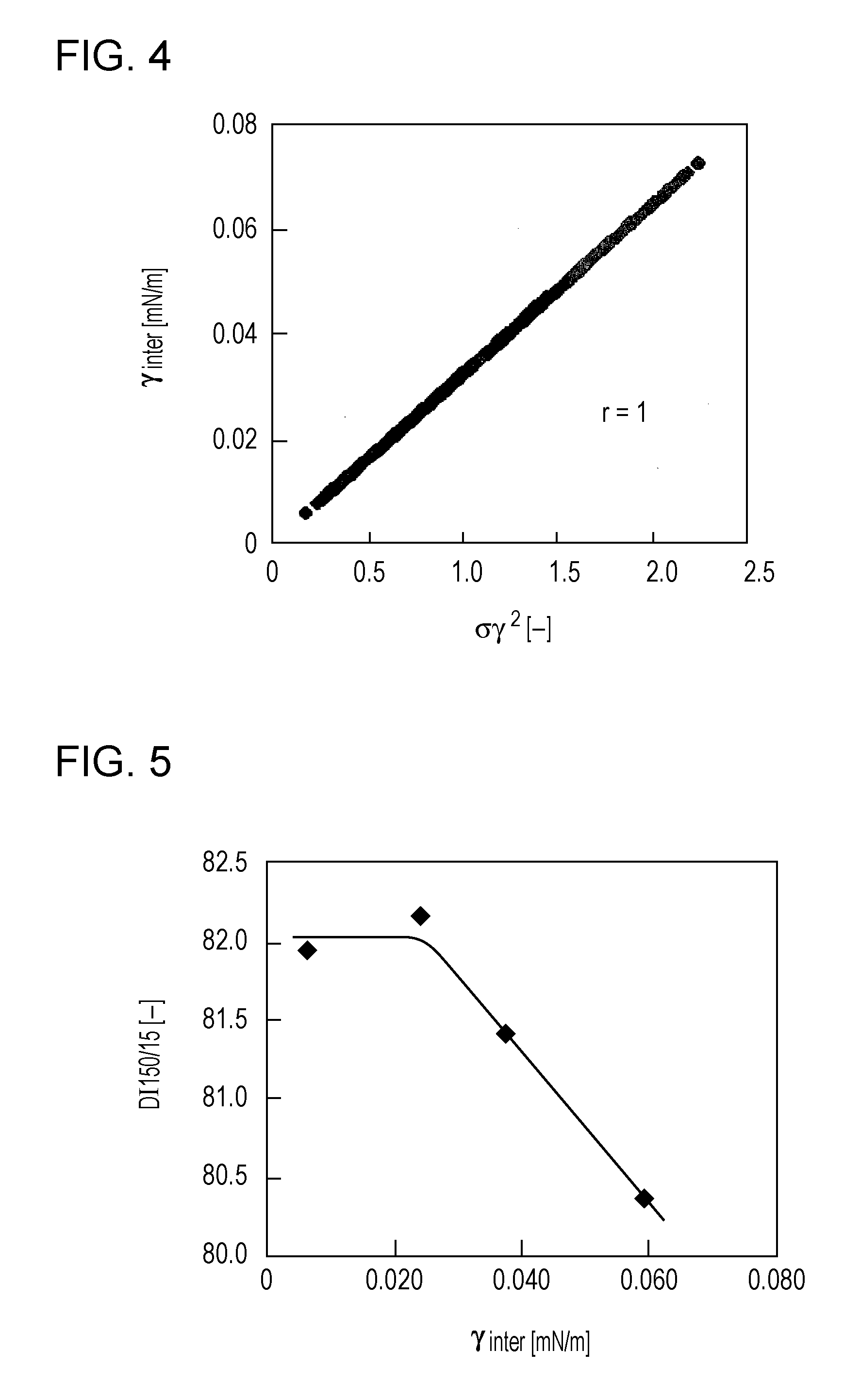
[0109]An example case where high strength coke was manufactured by controlling interfacial tension which is predicted from the variance of the surface tensions of all the kinds of coal constituting a coal blend. The same measurement items and the same results of the tests as used in [EXAMPLE 1] and [EXAMPLE 2] are used with the exception that interfacial tension is derived from equation (25). The calculation results of the interfacial tensions of blends A through I using equation (25) are given in Table 8.

[0110]

TABLE 8Blend Nameγinter by Equation (25)γinter by Equation (20)Blend A0.0060.006Blend B0.0240.024Blend C0.0370.037Blend D0.0590.059Blend E0.0010.001Blend F0.0030.003Blend G0.0140.014Blend H0.0220.022Blend I0.0030.003

[0111]For reference, γinter which was derived using equation (20) is also given in Table 8. As indicated by Table 8, it is confirmed that the value of γinter derived from equation (20) and that derived from equation (25) are almost the same. Therefore, it is consi...


PUM

PropertyMeasurementUnit
temperatureaaaaaaaaaa
reflectanceaaaaaaaaaa

Abstract

Coke is manufactured by blending two or more kinds of coal to form a coal blend and by carbonizing the coal blend. Interfacial tension among coal kinds is used as a control index for determining the blending ratio of each coal when forming the coal blend. It is possible to increase the strength of coke without increasing the material cost of a coal blend.

Description

CROSS-REFERENCE TO RELATED APPLICATIONS[0001]This is the U.S. National Phase application of PCT International Application No. PCT / JP2012 / 006526, filed Oct. 11, 2012, and claims priority to Japanese Patent Application No. 2011-226496, filed Oct. 14, 2011, the disclosures of each of these applications being incorporated herein by reference in their entireties for all purposes.FIELD OF THE INVENTION[0002]The present invention relates to a method for manufacturing high strength blast furnace coke.BACKGROUND OF THE INVENTION[0003]Blast furnace coke is used as a reducing agent, a heat resource, and a supporting material in order to keep gas permeability in a blast furnace. Nowadays, there is a trend toward manufacturing high strength coke so as to realize stable operation under the condition of a low reducing agent rate. Since plural kinds (ten kinds or more) of coal are typically blended and used when blast furnace coke is manufactured, investigations regarding a method for predicting th...

Claims


Application Information

Patent Timeline
Patent Type & Authority Patents(United States)
IPC IPC(8): C10B57/04C10B53/04C10B57/08C10B53/08C01B31/02C10L5/36
CPCC10B57/04C01B31/02C10L5/363C10B53/04C10B53/08C10B57/08C10L5/366C01B32/05G01N33/222
Inventor FUKADA, KIYOSHISUMI, HIROYUKISHIMOYAMA, IZUMIANYASHIKI, TAKASHIFUJIMOTO, HIDEKAZUYAMAMOTO, TETSUYADOHI, YUSUKE
Owner JFE STEEL CORP
Learn More