Electromagnetic actuator for optical device to reduce temperature and deformation

a technology of electromagnetic actuator and optical device, applied in the field of actuator, can solve the problems of reducing the lifetime of the actuation coil, affecting the actuation coil, and causing the illusion of inaccurately redirecting light, so as to reduce the amount of material required, reduce the electrical coupling, and reduce production costs

Active Publication Date: 2016-10-11
GOOGLE LLC
View PDF12 Cites 8 Cited by
  • Summary
  • Abstract
  • Description
  • Claims
  • Application Information

AI Technical Summary

Benefits of technology

[0006]According to the invention, there is provided an actuator comprising, a movable member, the movable member comprising a support frame which is configured such that it can oscillate about a first oscillation axis and a mirror which is fixed to the support frame such that oscillation of the support frame will effect oscillation of the mirror; a coil, which cooperates with the support frame; one or more boundary portions provided between the support frame and the mirror which reduce the influence of warp transmitted from an edge of the support frame to the mirror, as the support frame oscillates about the first oscillation axis; wherein the support frame further comprises one or more cut-out regions, wherein the one or more cut-out regions are configured to be parallel to at least a portion of the coil, to reduce stress on the coil as the support frame oscillates about the first oscillation axis.
[0007]The one or more cut-out regions may be further configured to reduce the temperature dependence of the properties of the actuator. For example, the cut out regions will provide a thermal barrier which will restrict the conduction of heat from the mirror to components such as the coil and / or torsional bars which cooperate with the support frame. Accordingly, the properties of the coil will be less affected by the increase in temperature of the mirror which occurs when the actuator is in use. Also reducing the temperature of the torsional bars will enable improved oscillation of the support frame. The cut-out regions may be filled by material presenting for example some specific thermo mechanical properties wherein the Young modulus of the material may vary with temperature in such a way that the properties of the actuator are independent of temperature changes which occur when the actuator is in use. The cut-out regions may be filled by material presenting for example some specific thermal properties absorbing the heating and thus reducing the heat propagation from the mirror to torsional bars which oscillate the support frame.
[0010]A “cut-out region” in the support frame is a region of the support frame which is provided with a through-hole, or is a region of the support frame which is provided with grooves. The cut out region may be elliptic, circular or with rounded corners. The grooves may be filled with a filler material which is different to the material from which the support frame is composed. The filler material may be configured to absorb energy which defines the stresses and strains or warp, which are created as the support frame oscillates about the first oscillation axis. For example, the filler material may comprise polyamide or polyimide material which has energy absorbing properties. Moreover the filler material may also be configured to have some heat absorption properties to reduce the temperature dependence of the actuator's performances e.g. to reduce the conduction of heat from the mirror to the coil and / or torsional bars. The filler material may be configured to absorb heating energy, caused due to external heating, so as to reduce the temperature sensitivity of the actuator's properties
[0022]The cut-out regions are arranged in the support frame to absorb warp which is transmitted from an edge of the support frame as the support frame oscillates. The cut-out regions are arranged in the support frame to absorb warp which is transmitted from an edge of the support frame as the support frame oscillates, before the warp reaches the coil. In same way the cut-out regions reduce the influence of the temperature on the properties of the actuator by providing some thermal isolation e.g. thermal isolation between the mirror and the coil and / or torsional bars.
[0024]The cut-out regions may be grooves. The grooves may further comprise filler material which is configured to absorb stresses in the support frame, caused due to oscillation of the support frame, so as to reduce the amount of stress on the coil as the support frame oscillates about the first oscillation axis. The filler material may be material which is different to the material from which the support frame is composed. The filler material may be configured to absorb warp which is transmitted from an edge of the support frame as the support frame oscillates. The filler material may also be configured to have some thermal properties, such as heat absorption properties, to reduce the temperature sensitivity of the actuator's performances.
[0046]The actuator may further comprise one or more spacing regions which are arranged between the support frame and second support frame. The space regions may be configured to reduce the electrical coupling between one or more coils on the support frame and one or more coils on the second support frame. Furthermore, advantageously, the one or more spacing regions will reduce the amount of material required to manufacture the actuator; thus the actuator will have reduced production costs. Moreover, the spacing regions will optimise the dynamic performance of the actuator by reducing the mass of the moveable member.

Problems solved by technology

Warp will cause distortion of mirror which ultimately causes the mirror to inaccurately redirect light, during operation.
However, it has not been recognised in the art, that oscillation of the support frame can also impart stress on the actuation coil.
These stresses can cause ware and tare of the actuation coil and will ultimately reduce the lifetime of the actuation coil.
Additionally, changes in the properties of the actuator due to a temperature changes, for example due to the laser heating in working condition, or due to a change in the ambient temperature, has not been recognised.
These changes in the properties of the actuator will reduce the quality of the actuator.

Method used


Image

  • Electromagnetic actuator for optical device to reduce temperature and deformation
  • Electromagnetic actuator for optical device to reduce temperature and deformation
  • Electromagnetic actuator for optical device to reduce temperature and deformation

Examples


Embodiment Construction

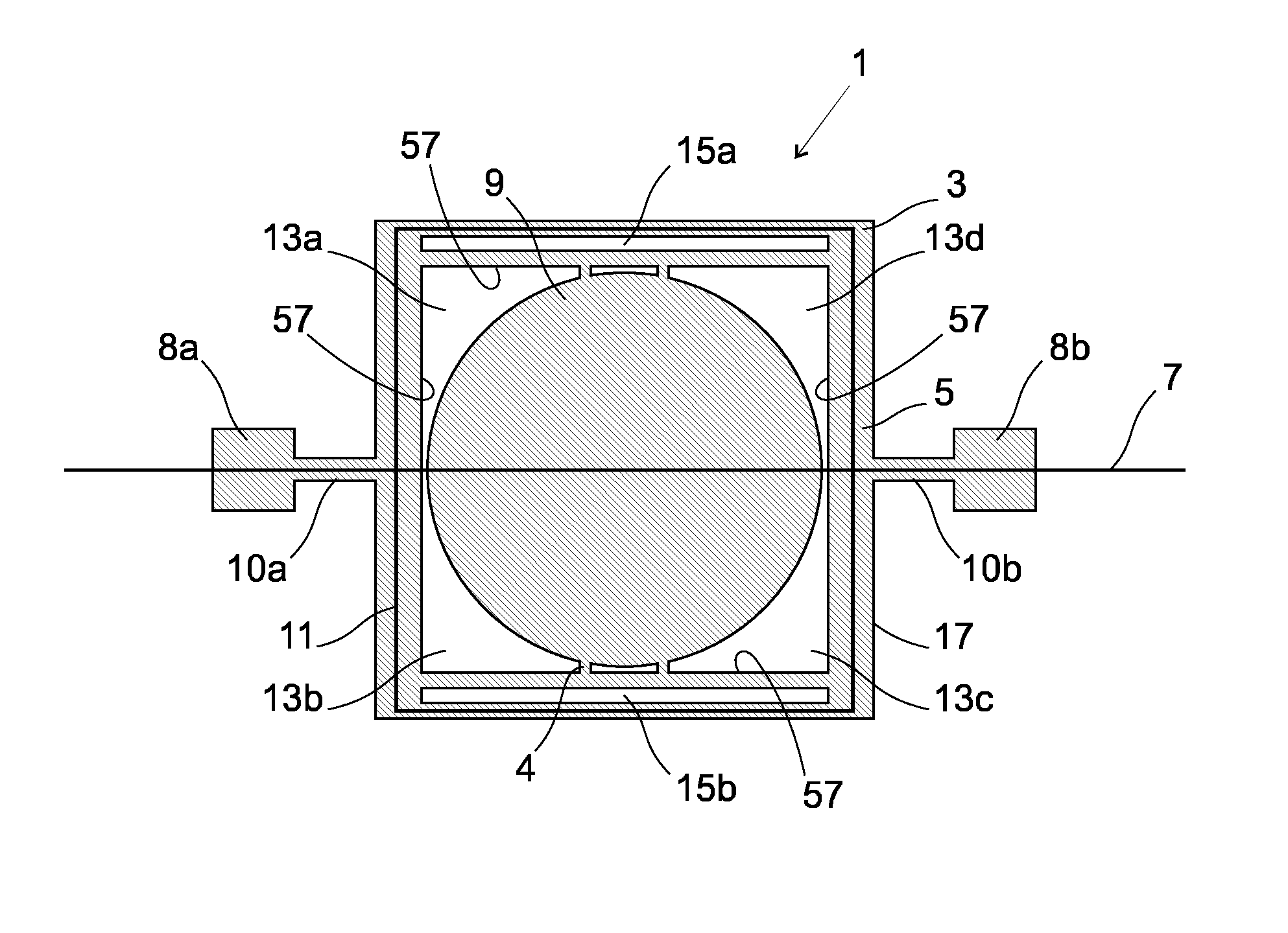
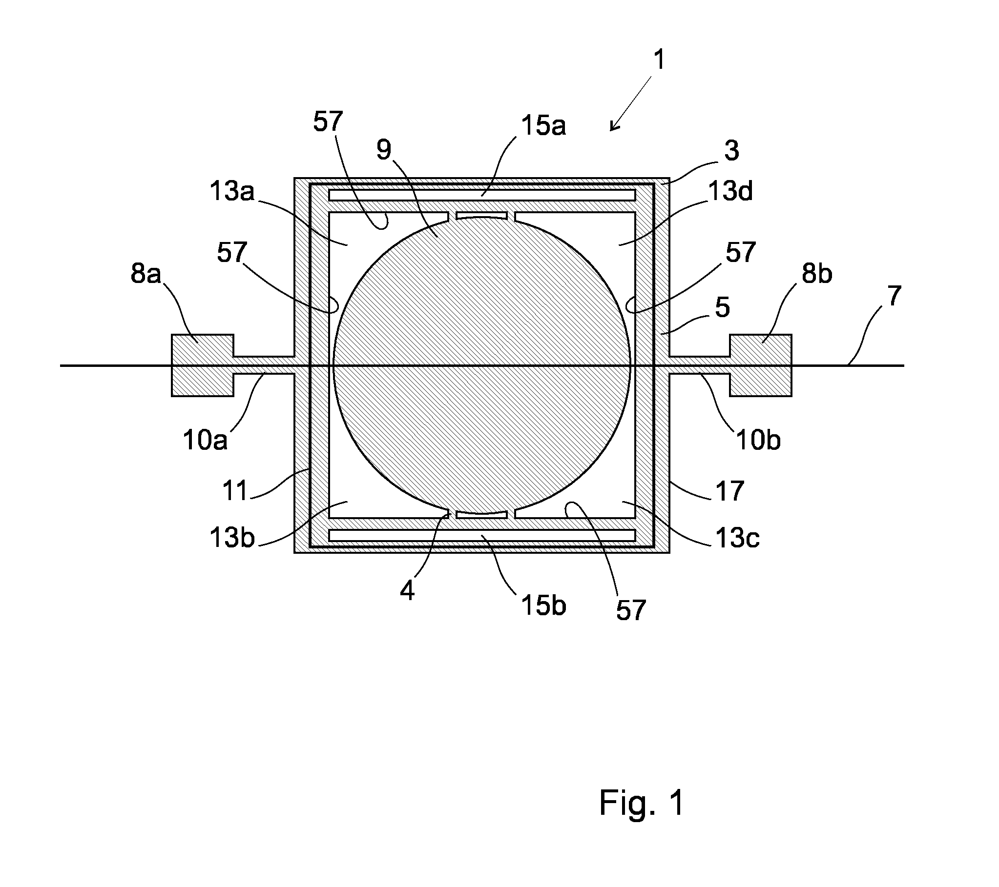
[0058]FIG. 1 shows an aerial view of an electromagnetic actuator 1 according to an embodiment of the present invention. The electromagnetic actuator 1 comprises a movable member 3. The movable member 3 comprises a support frame 5 which is configured such that it can oscillate about a first oscillation axis 7 and a mirror 9 which is fixed to the support frame 5 such that oscillation of the support frame 5 will effect oscillation of the mirror 9. The mirror 9 is fixed to the support frame 5 by means of connectors 4. The support frame 5 oscillates by means of torsional bars 10a, 10b which cooperate respectively with fixed portions 8a, 8b of the electromagnetic actuator 1.

[0059]The electromagnetic actuator 1 comprises an actuation coil 11, which cooperates with the support frame 5. It will be understood that the support frame 5 could be arranged in any other configuration; for example, the support frame could be arranged in a circular or oval configuration. The actuation coil 11 is arra...


PUM


Abstract

According to the present invention there is provided an actuator comprising, a movable member, the movable member comprising a support frame which is configured such that it can oscillate about a first oscillation axis and a mirror which is fixed to the support frame such that oscillation of the support frame will effect oscillation of the mirror; an coil, which cooperates with the support frame; one or more boundary portions provided between the support frame and the mirror which reduce the influence of warp transmitted from an edge of the support frame to the mirror, as the support frame oscillates about the first oscillation axis; wherein the support frame further comprises one or more cut-out regions, wherein the one or more cut-out regions are configured to be parallel to at least a portion of the coil, to reduce stress on the coil as the support frame oscillates about the first oscillation axis and / or to reduce the temperature dependence of the properties of the actuator.

Description

FIELD OF THE INVENTION[0001]The present invention concerns an actuator, in particular, but not exclusively, to an actuator which operates by applying an actuating signal to an actuation coil which cooperates with a support frame to effect oscillation of a support frame, wherein the support frame comprises cut-out regions which reduce stress on the actuation coil as the support frame oscillates and / or which reduce the temperature dependence of the actuator.DESCRIPTION OF RELATED ART[0002]Typically electromagnetic actuators which are used to oscillate mirrors, such as micro-mirrors, comprise a movable support frame on which the mirror is supported. The movable support frame is configured such that it can oscillate about an oscillation axis. An actuation coil cooperates with the support frame; the actuation coil is arranged such that it is submerged in a magnetic field provided by a magnetic component in the electromagnetic actuator. An actuation signal, which is typically in the form ...

Claims


Application Information

Patent Timeline
Patent Type & Authority Patents(United States)
IPC IPC(8): H02K33/00H02K33/16H02K33/02G02B26/08B81B3/00H02K9/22
CPCB81B3/0072G02B26/085G02B26/08H02K33/00H02K33/16H02K33/02B81B2201/038B81B2201/042B81B2203/058H02K9/22H02K9/227
Inventor GAMET, JULIENKHECHANA, FAOUZI
Owner GOOGLE LLC
Why Eureka
Try Eureka