Liquid crystal display device

a display device and liquid crystal technology, applied in optics, instruments, electrical appliances, etc., can solve the problems of not being able to disclose the documents 3 to 7 and the disclosure of the patent documents 3 to 7 to achieve the effect of non-uniform display, high display quality and effective realization

Active Publication Date: 2016-10-18
TOPPAN PRINTING CO LTD
View PDF47 Cites 1 Cited by
  • Summary
  • Abstract
  • Description
  • Claims
  • Application Information

AI Technical Summary

Benefits of technology

[0024]In the embodiment of the invention, display non-uniformity such as moiré can be eliminated, a three-dimensional image with a high display quality can be displayed, three-dimensional display and two-dimensional display can be switched, and three-dimensional display and two-dimensional display can be more brightly and effectively realized.

Problems solved by technology

Nor does patent document 1 disclose a technique of using liquid crystal molecules with a negative dielectric constant anisotropy in a liquid crystal display device for three-dimensional image display.
Nor does patent document 2 disclose a technique of using liquid crystal molecules with a negative dielectric constant anisotropy in a liquid crystal display device for three-dimensional image display.
However, none of patent documents 3 to 6 discloses a liquid crystal display device which optimizes light distribution by liquid crystal molecules per se, which are used in a liquid crystal panel, and enables bright three-dimensional image display and two-dimensional image display.
Thus, there is a case in which the OCB liquid crystal is not preferable for a liquid crystal display device for small-sized mobile equipment.
However, like patent document 8, none of patent documents 3 to 7 discloses a measure for eliminating moiré due to interference between the prism sheet and the liquid crystal panel, which tends to occur in three-dimensional image display.
Furthermore, none of patent documents 3 to 7 discloses a liquid crystal display device which optimizes light distribution by liquid crystal molecules per se, which are provided in a liquid crystal panel, and enables bright three-dimensional image display and two-dimensional image display.

Method used


Image

  • Liquid crystal display device
  • Liquid crystal display device
  • Liquid crystal display device

Examples


first embodiment

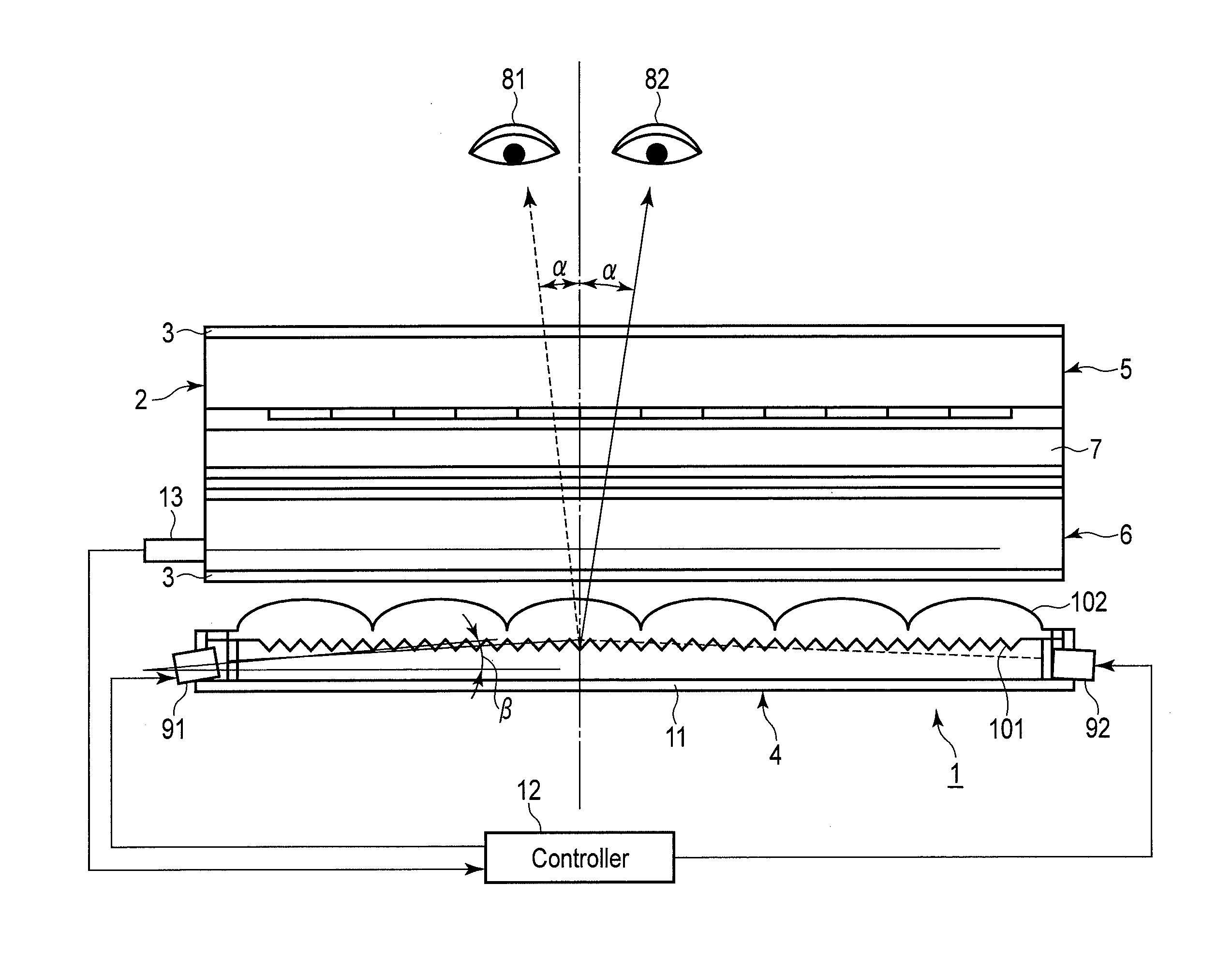
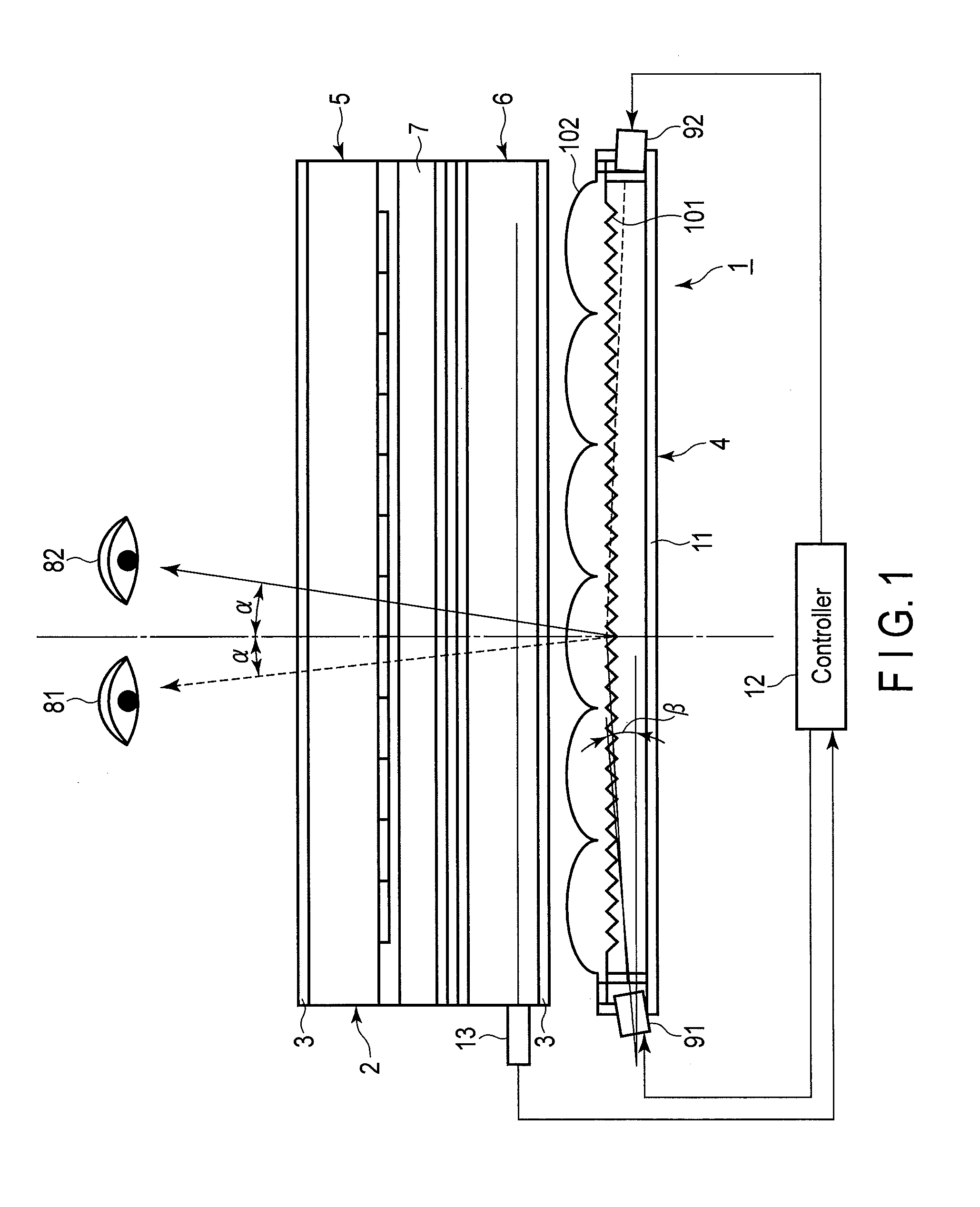
[0048]FIG. 1 is a cross-sectional view illustrating an example of a liquid crystal display device according to the embodiment. FIG. 1 shows a cross section in the lateral direction.

[0049]A liquid crystal display device 1 includes, as basic structural elements, a liquid crystal panel 2, polarizers 3, a backlight unit 4, and a controller 12. The polarizer 3 may be formed by attaching a retardation plate.

[0050]In each of the embodiments below, a pair of polarizers 3 may be configured as crossed Nicols. In addition, the absorption axes of the paired polarizers 3 may be made parallel, and the liquid crystal display device 1 may include a spiral element between one of the polarizers 3 and the liquid crystal panel 2, the spiral element being configured to convert first linearly polarized light of this one of the polarizers 3 to second linearly polarized light which is perpendicular to the first linearly polarized light.

[0051]The liquid crystal panel 2 includes a color filter substrate 5, a...

second embodiment

[0129]The present embodiment is a modification of the first embodiment, and a description is given of a liquid crystal display device further including a transparent electrode film between the transparent substrate 15 of the color filter substrate and the color filter 16.

[0130]FIG. 13 is a cross-sectional view illustrating an example of a liquid crystal display device according to the present embodiment. FIG. 13 is a cross-sectional view in the lateral direction.

[0131]FIG. 14 is a cross-sectional view illustrating an example of a liquid crystal display device 30 according to the second embodiment.

[0132]The liquid crystal display device 30 includes, as basic structural elements, a liquid crystal panel 26, polarizers 3, and a backlight unit 27. Incidentally, like the liquid crystal display device 1 according to the above-described first embodiment, the liquid crystal display device 30 may include a controller 12 and a light reception element 13.

[0133]Solid-state light emission element...

third embodiment

[0163]In the present embodiment, transparent resins and organic pigments, which are used for the color filter substrates 5, 28 according to the above-described first and second embodiments, will be exemplarily described.

[0164](Transparent Resins)

[0165]A photosensitive color composition, which is used for forming the black matrix BM and color filter 16, includes, in addition to a pigment-dispersed body, a multifunctional monomer, a photosensitive resin or a nonphotosensitive resin, a polymerization initiator, and a solvent. Organic resins with high transparency which can be used in the present embodiment, for instance, a photosensitive resin or a nonphotosensitive resin, are generally referred to as transparent resins.

[0166]As the transparent resins, use can be made of thermoplastic resins, thermosetting resins, or photosensitive resins. As the thermoplastic resins, for example, use can be made of a butyral resin, styrene-maleic acid copolymer, chlorinated polyethylene, chlorinated p...


PUM

PropertyMeasurementUnit
angleaaaaaaaaaa
angleaaaaaaaaaa
angleaaaaaaaaaa

Abstract

A device according to an embodiment includes an array substrate including electrodes corresponding to pixels arranged in a matrix, a color filter substrate opposed to the array substrate and including color filters corresponding to the pixels, a liquid crystal layer provided between the substrates, a backlight, and a controller which controls the substrates and the backlight. The pixels are configured to each have a parallelogrammatic shape elongated in a lateral direction, such that identical colors are arranged in the lateral direction, and different colors are arranged in a vertical direction. Pixels neighboring in the lateral direction are in line-symmetry with respect to a center line of the neighboring pixels. Liquid crystal molecules have negative dielectric constant anisotropy, and rotate horizontally relative to a substrate plane in a direction of the line-symmetry with respect to the center line when the voltage is applied to the electrodes of the neighboring pixels.

Description

CROSS-REFERENCE TO RELATED APPLICATIONS[0001]This application is Continuation application of PCT Application No. PCT / JP2013 / 057886, filed Mar. 19, 2013 and based upon and claiming the benefit of priority from the Japanese Patent Application No. 2012-094960, filed Apr. 18, 2012, the entire contents of all of which are incorporated herein by reference.BACKGROUND OF THE INVENTION[0002]1. Field of the Invention[0003]The present invention relates to a liquid crystal display device.[0004]2. Description of the Related Art[0005]A liquid crystal cell of a general liquid crystal display device has a structure in which a liquid crystal layer is held by transparent substrates such as glass substrates. The liquid crystal display device includes a liquid crystal panel configured such that a polarizer, or a polarizer and a retardation plate, are disposed on the front and back of the liquid crystal cell.[0006]In a first example, a liquid crystal display device includes a backlight unit as a light s...

Claims


Application Information

Patent Timeline
Patent Type & Authority Patents(United States)
IPC IPC(8): G09G3/36G02F1/133G02F1/1335G02F1/29G02F1/1337G02F1/137H04N13/04G02F1/1343G02F1/1368
CPCG09G3/3696G02F1/137G02F1/1368G02F1/13306G02F1/13439G02F1/133512G02F1/133514G02F1/133615G02F1/133707G02F1/134336G02F1/134363G02F1/292G09G3/3607H04N13/0404H04N13/0454H04N13/0468G02F2001/13712G02F2001/133607H04N13/0422H04N13/305H04N13/324H04N13/359H04N13/366G02F1/133607G02F1/13712G02F1/1343
Inventor SHIMA, YASUHIRONAKADA, HISASHIFUKUYOSHI, KENZO
Owner TOPPAN PRINTING CO LTD
Why Eureka
Try Eureka