
System and method for structural rehabilitation and enhancement

a structural rehabilitation and enhancement technology, applied in the direction of building repairs, construction, building structures, etc., can solve the problems of structural integrity damage, structural integrity damage, structural damage, etc., and achieve the effect of providing compressive strength

Active Publication Date: 2016-10-25
ABBASI SEYED HOSSEIN +1
View PDF12 Cites 1 Cited by
  • Summary
  • Abstract
  • Description
  • Claims
  • Application Information

AI Technical Summary

Benefits of technology

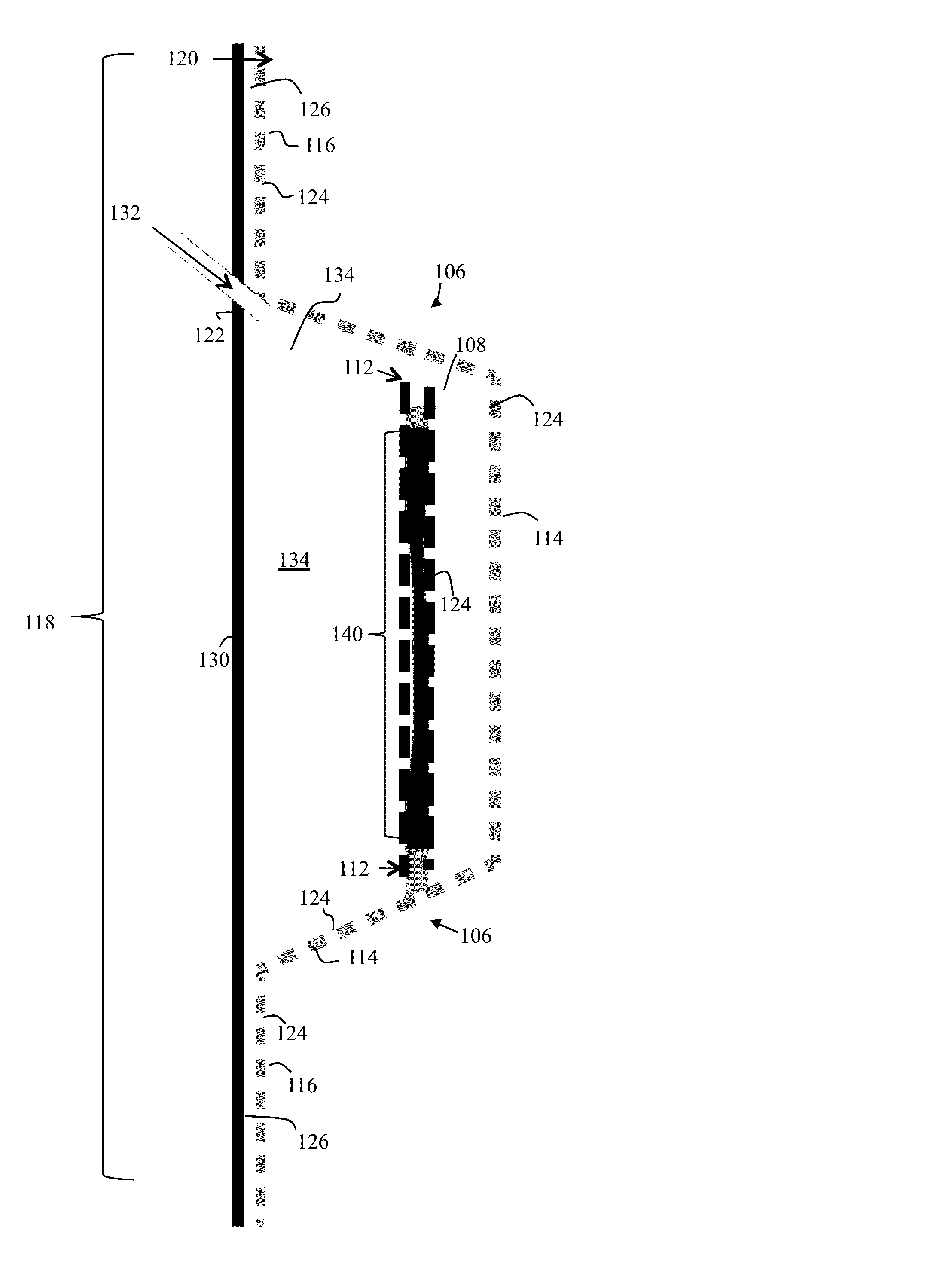
[0026]the filler encapsulates a deteriorated reinforcement, binds to all surfaces with which the filler contacts, and provides compressive strength for the reinforced structure while the tensile member provides a tensile strength.

Problems solved by technology

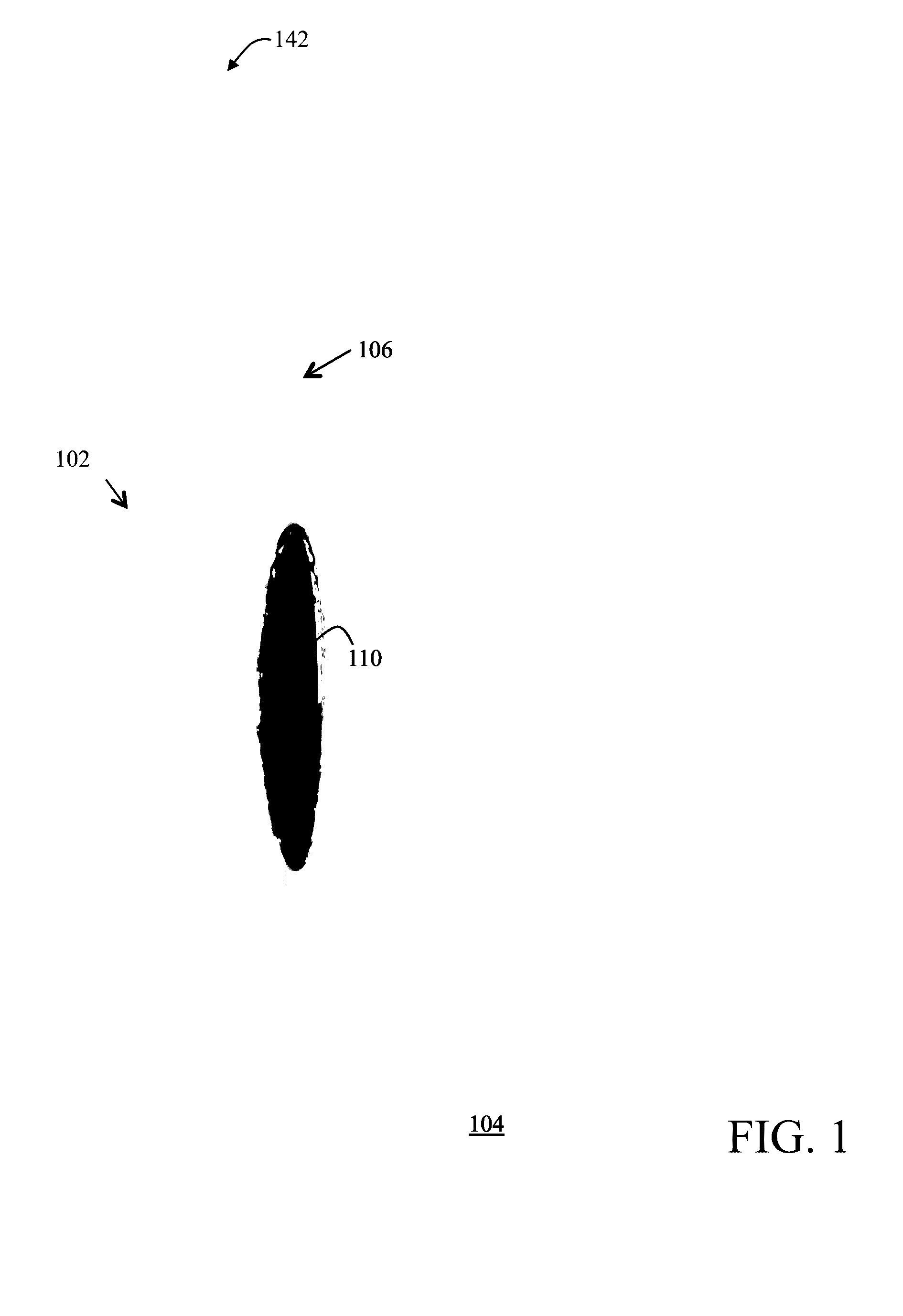
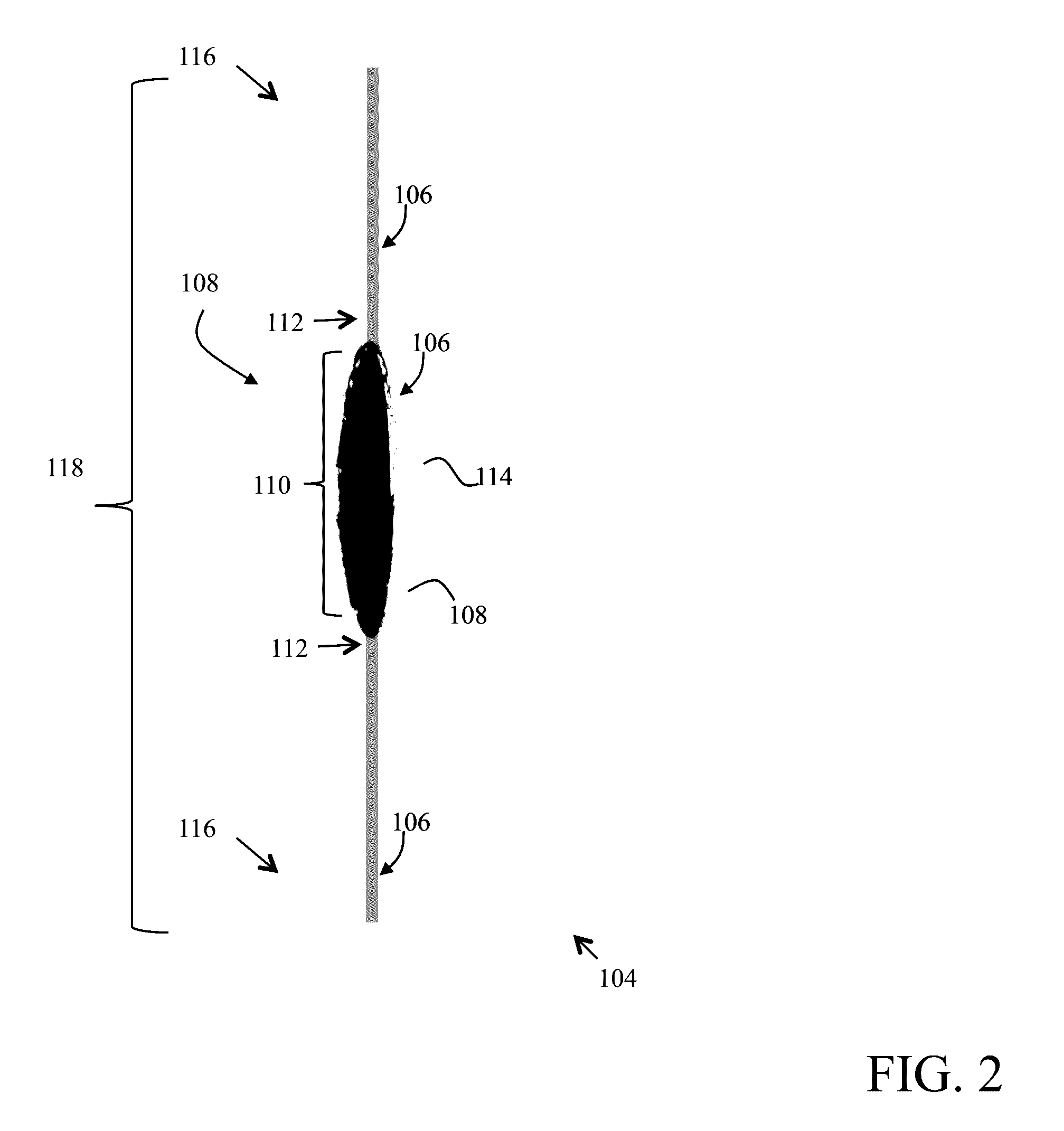
Structural integrity of reinforced concrete structures is severely compromised due to spalling.
In general, spalling is caused due to corrosion of the reinforcement, which is generally a reinforcing bar (or rebar for short) that is a metal or a metallic alloy most likely comprised of steel.
When the reinforcement corrodes, it rusts (and crumbles) and therefore, expands in volume within the concrete structure, causing spalling.
Additionally, loose pieces of rust particles (or crumbles) of the reinforcement also cause the concrete structure to lose its mechanical bond with the reinforcement, making the reinforcement ineffective.
A further issue with corrosion of the reinforcement is that as the reinforcement corrodes into crumbling rust, the amount of reinforcement left is degraded, weakening the structural integrity of the reinforced concrete structure.
In general, the conventional repairing processes of spalled reinforced concrete structures involved many labor-intensive steps that are complex and require skilled labor, which adds to the overall cost of the structural rehabilitation.
Additionally, if the extent of the corrosion of the rebar observed is severe (e.g., where the integrity of the rebar is fully compromised, making it ineffective), the cavity should be further extended axially along the rebar to expose even more of the non-corroded portion thereof to enable augmentation of the rebar using well known splicing methodologies (detailed below).
It should be noted that completely cleaning of the rebar from corrosion and removal of all rust (e.g., by scraping) is very time consuming and labor intensive.
The augmentation of a rebar is a complex, labor intensive, and time-consuming process that uses well known splicing methodologies, resulting in a lap spliced rebar.
For conventional methods, if the cavity is small, it is generally more cost effective to patch the cavity using well-known methodologies such as multi-lift patching, which itself is very time consuming, especially if the number of repairs is large.
The quality of multi-lift patching process is generally poor due to potentially weak bonding properties between patched layers.
However, prior to pouring of the mortar, forming structures are used for forming the poured mortar to fill the excavated cavity and allow the mortar to be cured flush with exterior surface of the concrete structure, which requires time and materials to construct.
This is especially difficult for non-flat surfaces such as reinforced concrete support columns that are generally cylindrical and hence, the wood forming structure must somehow be built to enable the mortar to be flush with the surface of the cylindrically or other odd-shaped structures.
This phase of the overall conventional rehabilitations process becomes complex if the opening is oriented at a direction where the forming structure must be secured against gravity.
The removal of the forming structure is not a simple task as it may require heavy machinery and skilled labor.
For example, the corrosion protection material used should not chemically interact with the mortar material, which may result in a degraded the integrity of both.

Method used


Image

  • System and method for structural rehabilitation and enhancement
  • System and method for structural rehabilitation and enhancement
  • System and method for structural rehabilitation and enhancement

Examples


Embodiment Construction

[0039]The detailed description set forth below in connection with the appended drawings is intended as a description of presently preferred embodiments of the invention and is not intended to represent the only forms in which the present invention may be constructed and or utilized.

[0040]It is to be appreciated that certain features of the invention, which may, for clarity, be described in the context of separate embodiments, may also be provided in combination in a single embodiment. Conversely, various features of the invention that may, for brevity, be described in the context of a single embodiment may also be provided separately or in any suitable sub-combination or as suitable in any other described embodiment of the invention. Stated otherwise, although the invention is described below in terms of various exemplary embodiments and implementations, it should be understood that the various features and aspects described in one or more of the individual embodiments are not limit...


PUM

PropertyMeasurementUnit
sizeaaaaaaaaaa
widthaaaaaaaaaa
corrosionaaaaaaaaaa

Abstract

The present invention discloses system and method for rehabilitation and enhancement of structural integrity of a reinforced concrete structures, comprising exposing beyond a deteriorated portion of a reinforcement where a non-deteriorated portion is visible, covering a surround of the exposed reinforcement by a tensile member that is coupled with an exterior surface of the reinforced concrete structure, and encapsulating the exposed reinforcement, with the encapsulation formed by the tensile member.

Description

CROSS-REFERENCE TO RELATED APPLICATIONS[0001]This application claims the benefit of priority of U.S. Utility Provisional Patent Application No. 62 / 010,356, filed 10 Jun. 2014, the entire disclosure of which is expressly incorporated by reference in its entirety herein.[0002]It should be noted that where a definition or use of a term in the incorporated patent application is inconsistent or contrary to the definition of that term provided herein, the definition of that term provided herein applies and the definition of that term in the incorporated patent application does not apply.BACKGROUND OF THE INVENTION[0003]1. Field of the Invention[0004]One or more embodiments of the present invention relate to cost effective structural rehabilitation and enhancement.[0005]2. Description of Related Art[0006]Structural integrity of reinforced concrete structures is severely compromised due to spalling. In general, spalling is caused due to corrosion of the reinforcement, which is generally a r...

Claims


Application Information

Patent Timeline
Patent Type & Authority Patents(United States)
IPC IPC(8): E04G23/02E04G23/00
CPCE04G23/0218E04G23/02E04G23/0203E04G23/0266E04G2023/0251
Inventor ABBASI, SEYED HOSSEINABBASI, NEIL JAVAD
Owner ABBASI SEYED HOSSEIN
Learn More