Eureka AIR delivers breakthrough ideas for toughest innovation challenges, trusted by R&D personnel around the world.

Sealed pressure-measuring member

a pressure-measuring member and sealing technology, applied in the field of pressure sensors, can solve the problems of painstaking and costly exercise, unusable member, and inability to use, and achieve the effect of reliable pressure-measuring

Active Publication Date: 2016-10-25
MICHELIN & CO CIE GEN DES ESTAB MICHELIN
View PDF19 Cites 5 Cited by
  • Summary
  • Abstract
  • Description
  • Claims
  • Application Information

AI Technical Summary

Benefits of technology

The invention is a pressure measuring device that has a protective housing to prevent damage to the pressure measuring surface. The device has an overhanging skirt that can flex and deform to remove any debris or particles that may get trapped between the parts or enter the protective housing. This helps to ensure accurate pressure readings and eliminates the need for calibration.

Problems solved by technology

However, repeated mechanical loadings applied by the indentation to the test body upon contact therewith lead firstly to wear on the test body, thus impairing the pressure measurement, and secondly to detachment of the test body from its support, thus rendering the member unusable.
Further, because the member is of a passive type, each measurement member has to be calibrated once it has been manufactured, and this is therefore a painstaking and costly exercise.
That increases the complexity and cost of the system.
Further, the calibration data are a source of measurement errors.
It should also be noted that, when the member is not completely sealed throughout its entire life, it is not protected from chemical attack, notably from attack by the products used for maintaining the rims and the tyre.
This prolonged exposure to chemical attack impairs the test body and therefore the pressure measurement.

Method used


Image

  • Sealed pressure-measuring member
  • Sealed pressure-measuring member
  • Sealed pressure-measuring member

Examples


first embodiment

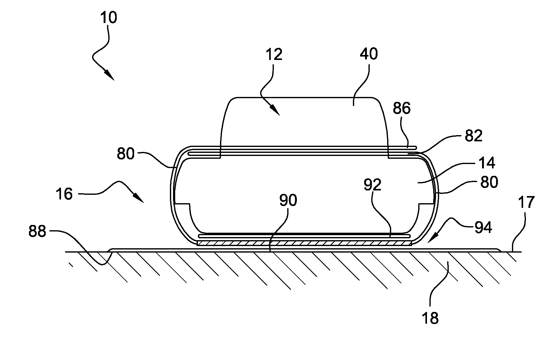
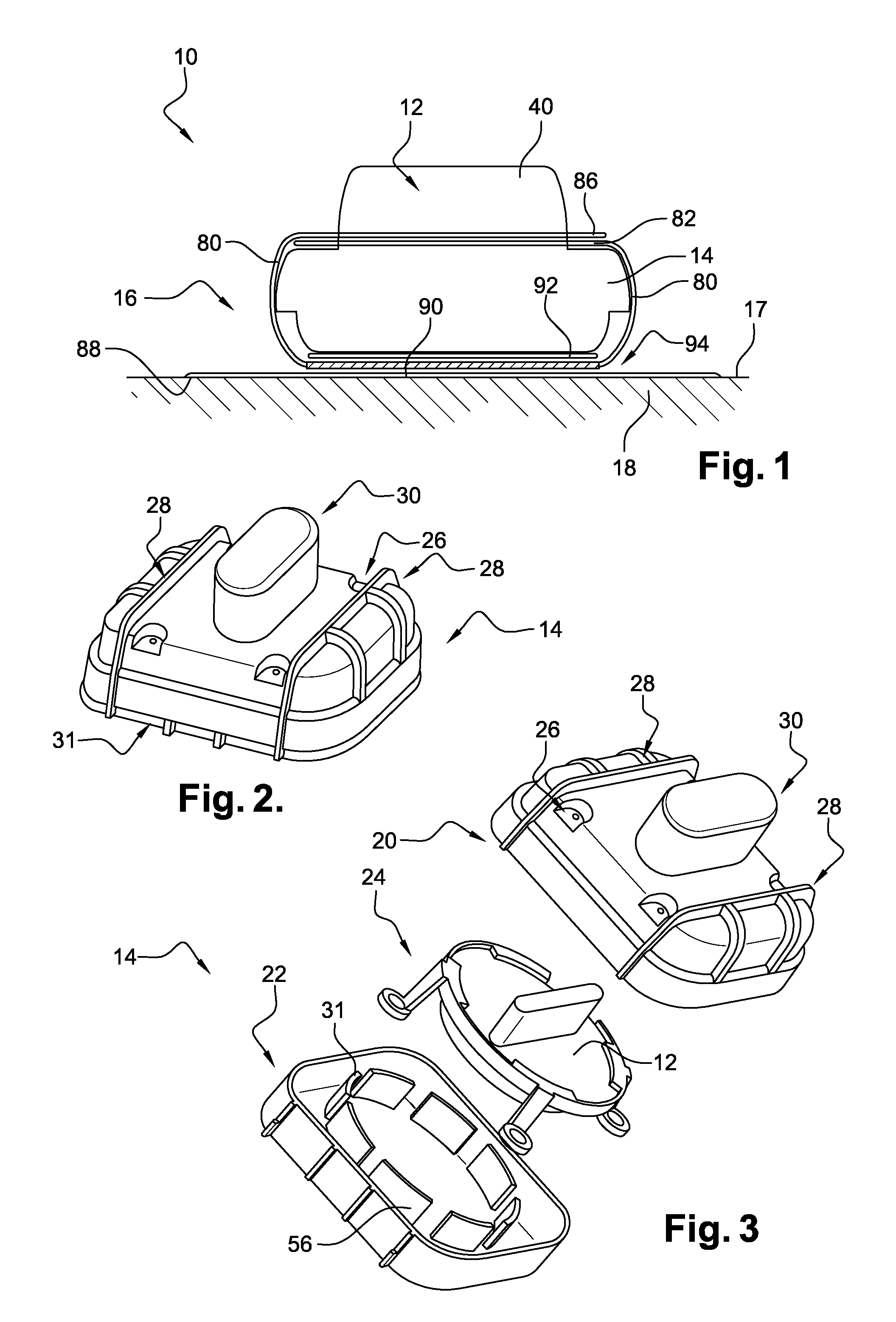
[0063]FIG. 1 depicts a device and denoted by the overall reference 10. The device 10 comprises a pressure-measurement member 12 and a protective housing 14 for protecting the measurement member 12. The device 10 also comprises means 16 for securing the protective housing 14 to an internal surface 17 of a tyre 18. The tyre 18 is used for construction work applications.

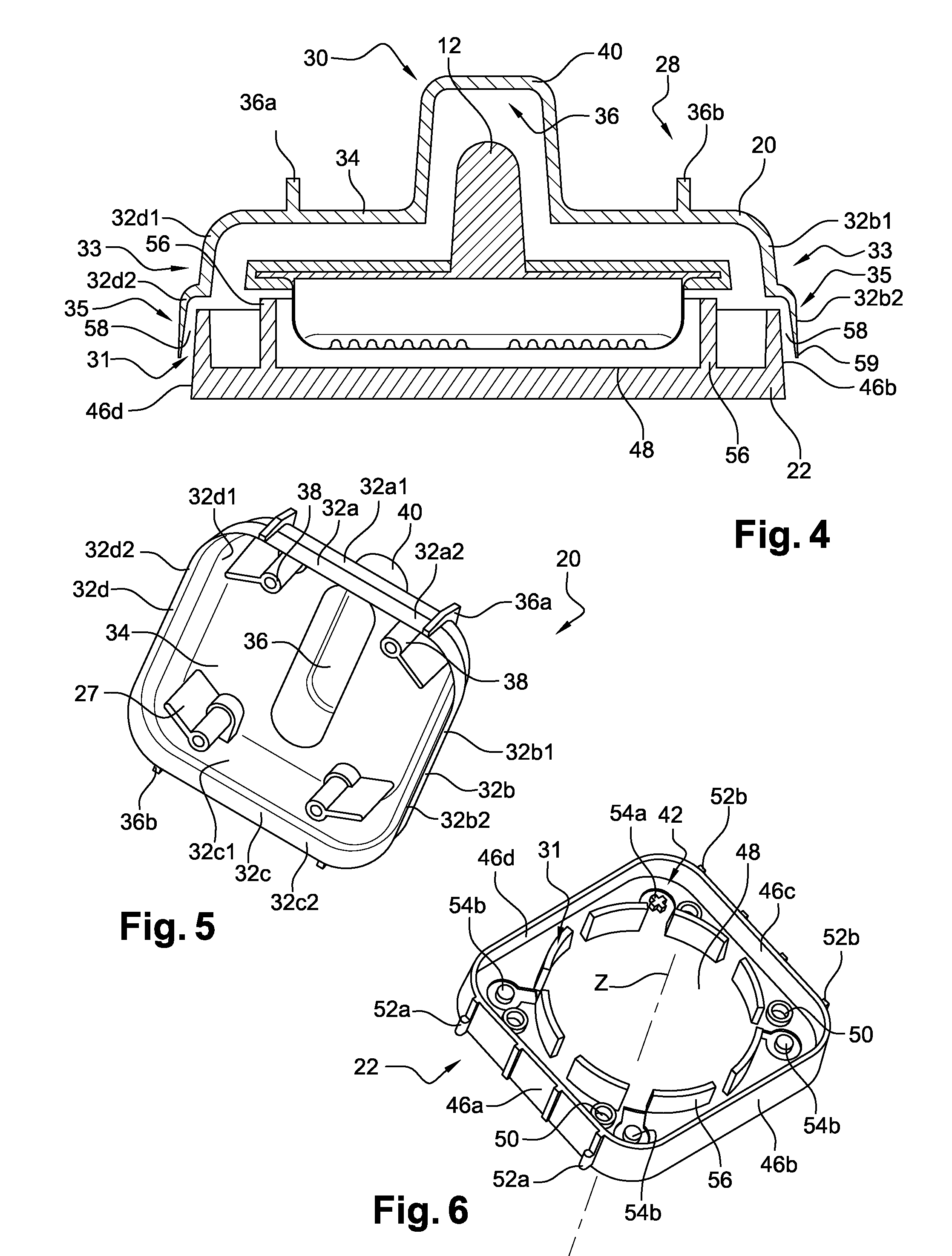
[0064]With reference to FIGS. 2 to 4, the protective housing 14 comprises first and second parts 20, 22. The device 10 comprises a positioning support 24 for positioning the member 12 in the housing 14. The parts 20, 22 are able to move, in this particular instance are able to be detached, relative to one another and are arranged in such a way that they allow air to communicate between the outside and the inside of the housing 14 when they are assembled, for example via a space between the two parts 20, 22. The parts 20, 22 are able to move one relative to the other between a position for inserting the member 12 into t...

second embodiment

[0094]FIG. 13 depicts a device according to the invention. Elements that are analogous with those depicted in the previous figures are denoted by identical references.

[0095]In this second embodiment, the securing means 16 comprise a patch 142 bearing a male slide of trapezoidal section 144 on its face 90. The means 16 also comprise a slide, of female trapezoidal section, 146 formed in the second part 22. The device 10 according to the second embodiment also comprises means 148 of locking the housing 14 with the patch 142. The locking means 148 comprise an oblong orifice 150 formed in a lug 152 borne by one of the walls of the part 22. The means 148 also comprise a pair of elastic hooks 154 intended to be inserted into the orifice 150 when the orifice 150 passes beyond a locking wall 156 of the male slide 144.

[0096]The invention is not restricted to the embodiments previously described.

[0097]In particular, a device 14 could be used that has a means of connection other than those desc...


PUM


Abstract

A pressure-measurement device includes a pressure-measurement surface, which is functionally connected to a test body, and a sealed pressure-measurement housing in which the test body is arranged. The pressure-measurement surface is carried by a deformable wall of the sealed pressure-measurement housing lying at a distance from the test body. The sealed pressure-measurement housing delimits an internal space, which is a space internal to the sealed housing. The pressure-measurement device also includes a pressure-transmission object that transmits the pressure between the pressure-measurement surface and the test body. The pressure-transmission object includes a substantially incompressible material occupying all of the internal space. The pressure-measurement device further includes an energy source and a processor for processing pressure data detected by the test body. The processor is arranged in the sealed pressure-measurement housing.

Description

FIELD OF THE INVENTION[0001]The present invention relates to the field of pressure sensors.BACKGROUND[0002]The invention applies, without being restricted thereto, to the measurement of tyre pressure, in particular for construction machinery tyres.[0003]The prior art, notably U.S. Pat. No. 6,931,934, discloses a pressure-measurement member arranged inside the space delimited by the tyre and the rim. The member is of a passive type and comprises a protective housing. The member also comprises a test body and the housing comprises a wall supporting a pressure-measurement surface functionally connected to the test body. Specifically, this wall comprises an indentation designed so that the wall is positioned in contact with the test body. Under the effect of the external pressure applied to the wall, the indentation mechanically transmits the pressure to the test body which is therefore able to detect the pressure external to the member.[0004]However, repeated mechanical loadings applie...

Claims


Application Information

Patent Timeline
IPC IPC(8): G01L19/08G01L17/00B60C23/04G01L19/06
CPCG01L19/086B60C23/0493G01L17/00G01L19/0645G01L19/143G01L19/144
Inventor CHAMPREDONDE, JONATHANLEMAN, RICHARDLEMAN, MARKSMITH, PETER
Owner MICHELIN & CO CIE GEN DES ESTAB MICHELIN
Why Eureka
Eureka Blog
Learn More