Optical device

a technology of optical devices and optical components, applied in the field of optical devices, can solve the problems of large light loss and the sudden change of the mode field diameter of light of at least one of the modes, and achieve the effect of suppressing light loss

Active Publication Date: 2016-10-25
FUJIKURA LTD +1
View PDF10 Cites 2 Cited by
  • Summary
  • Abstract
  • Description
  • Claims
  • Application Information

AI Technical Summary

Benefits of technology

[0011]An object of the present invention is therefore to provide an optical device capable of suppressing light loss.
[0013]With this optical device, light propagating through one side that is not tapered of each core toward the other side thereof that is tapered propagates through the inner core, diffuses to the outer core at a position at the tapered portion and propagates through the entire core combining the inner core and the outer core. In this case, since the refractive index of the inner core is such that the low-refractive-index portion is surrounded by the high-refractive-index portion, the light intensity profile of light in the LP01 mode diffuses toward the outer circumference of the core more easily than a case in which the refractive index of the core is uniform. Light in the LP01 mode can therefore be easily switched from the state propagating through the inner core to the state propagating through the entire core combining the inner core and the outer core with the tapering of the core. Furthermore, light in another mode can also be switched from the state propagating through the inner core to the state propagating through the entire core combining the inner core and the outer core with the tapering of the core. In this manner, light in the LP01 mode can be suppressed from remaining in the inner core in a state in which the core is tapered, and emission of light in a state in which the mode field diameters of lights in the respective modes are greatly different can be suppressed, and light loss can be suppressed.
[0019]Alternatively, the low-refractive-index portion may have a refractive index equal to the refractive index of the cladding. With such a structure, when the refractive index of the cladding is equivalent to the refractive index level of pure quartz, the low-refractive-index portion can be produced without adding any additive to quartz, which makes control of refractive indices and production of glass easier.
[0021]The present inventors have found that, when the optical device satisfies the aforementioned condition, the mode field diameter of light in the LP01 mode is substantially equal at the entrance side and the emission side and the mode field diameter of light in the LP11 mode is substantially equal at the entrance side and the emission side. The management of the mode field diameter of light therefore becomes easier in conducting multimode communication using light in the LP01 mode and light in the LP11 mode, and the multimode communication using lights in these modes can therefore be easily conducted.
[0023]As described above, according to the present invention, an optical device capable of suppressing light loss is provided.

Problems solved by technology

When emitted light having different field mode diameters between light in the LP01 mode and light in the LP11 mode enters a multicore fiber connected to the optical device, the mode field diameter of light of at least one of the modes is likely to suddenly change after entering the multicore fiber and light loss is likely to be large.

Method used


Image

  • Optical device
  • Optical device
  • Optical device

Examples


first embodiment

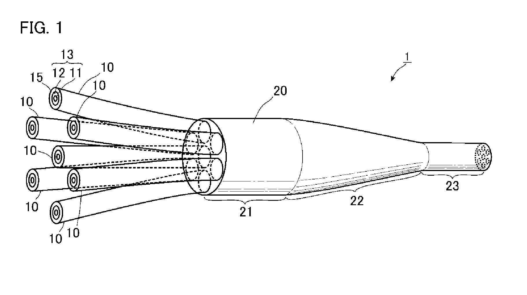
[0039]FIG. 1 is a view illustrating an optical device according to a first embodiment of the present invention. As illustrated in FIG. 1, an optical device 1 of the present embodiment includes multiple relay fibers 10 and a capillary 20 as main components. In this example, the number of relay fibers 10 is seven.

[0040]The relay fibers 10 are inserted into the capillary 20 from one end to the other end thereof, and the relay fibers 10 and the capillary 20 are integrated without any gap therebetween. Parts of the relay fibers 10 that are not inserted into the capillary 20 are exposed.

[0041]The capillary 20 is circular in cross-section, and includes a large diameter portion 21, a tapered portion 22, and a small diameter portion 23 formed along the longitudinal direction. Such a shape is formed as follows. First, a capillary having through-holes formed therein and having a constant thickness is provided, the number of through-holes being the number of relay fibers 10 to be inserted, and ...

second embodiment

[0053]Next, a second embodiment of the present invention will be described. Here, components that are identical or similar to those in the first embodiment are designated by the same reference numerals and redundant description will not be repeated unless the description is particularly stated.

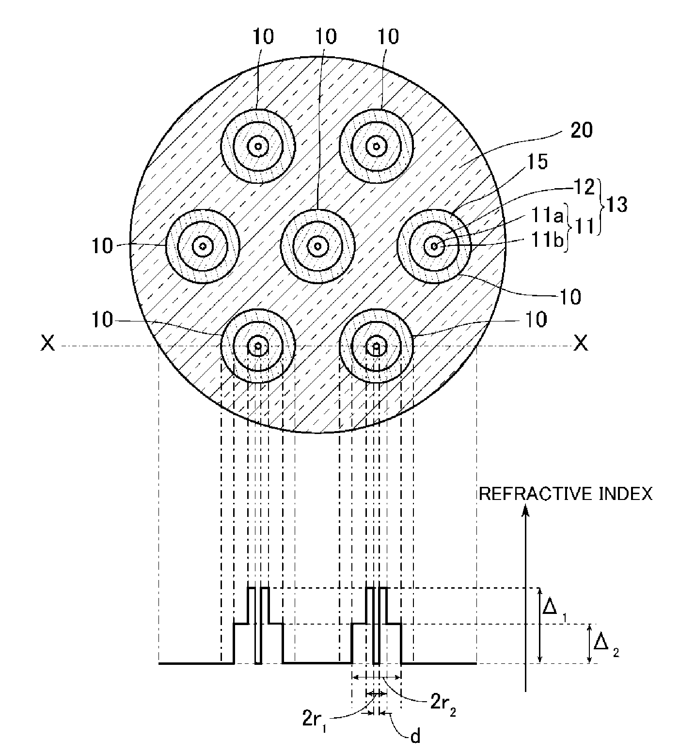
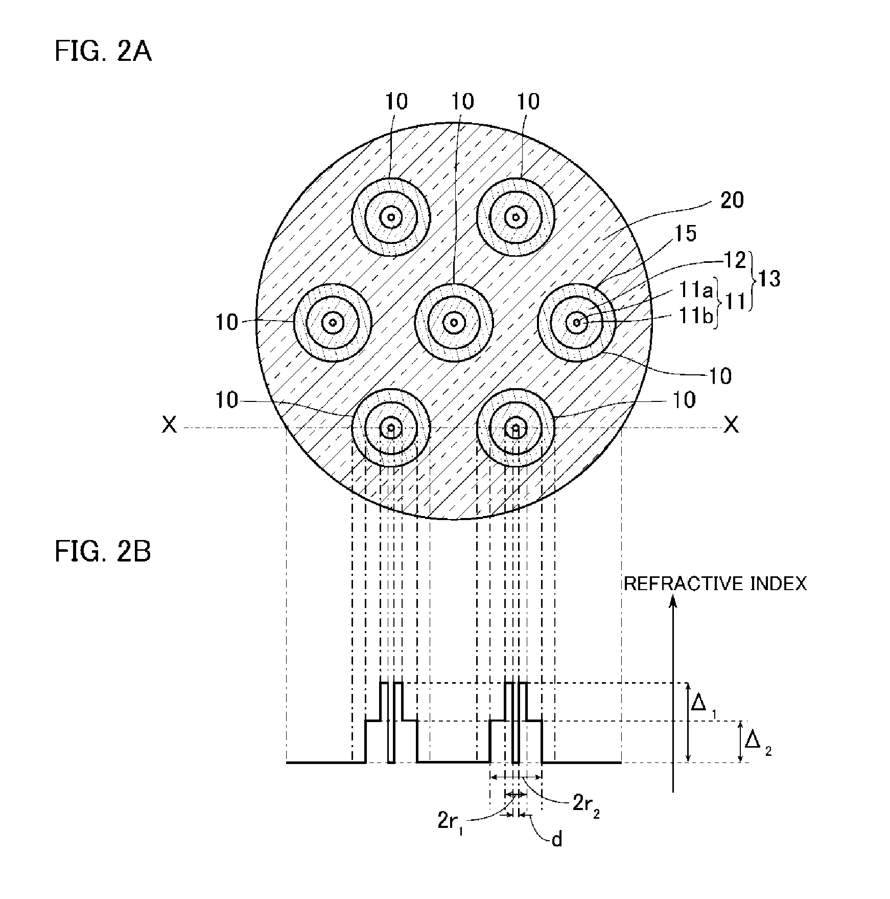
[0054]FIG. 4 is a view illustrating an optical device according to the second embodiment of the present invention, and FIGS. 5A and 5B are diagrams illustrating a state of a cross section perpendicular to the longitudinal direction of the optical device 2 of FIG. 4. As illustrated in FIGS. 4, 5A, and 5B, the optical device 2 of the present embodiment is different from the optical device of the first embodiment in that the outer circumferential surface of the core 13 is surrounded by cladding 25 made of the same glass material as the capillary 20 of the first embodiment without any space therebetween and that the core 13 is positioned only in the cladding 25. Specifically, the optical device 2 ...

example 1

[0063]A simulation is conducted using the optical device 1 of the first embodiment as a model. In the present model, the low-refractive-index portion 11a had a refractive index equal to that of the cladding 15 similarly to the first embodiment. Furthermore, the ratio (d / 2r1) of the diameter d of the low-refractive-index portion 11a of the inner core 11 to the outer diameter 2r1 of the high-refractive-index portion 11b is set to 0.3.

[0064]Subsequently, conditions under which the effective area Aeff of light in the LP01 mode is 110 μm2 and the effective area Aeff of light in the LP11 mode is 170 μm2 at the large diameter portion 21 are obtained. Specifically, the radius r1 of the inner core 11 and the relative refractive index difference Δ1 of the high-refractive-index portion 11b from the cladding 15 are obtained for each of the cases where the relative refractive index difference Δ2 of the outer core 12 from the cladding 15 is 0.5, 1.0, and 1.5. The result is shown in Table 1.

[0065]...


PUM


Abstract

An optical device includes: multiple cores each including an inner core and an outer core surrounding an outer circumferential surface of the inner core without any gap therebetween; and cladding surrounding an outer circumferential surface of the cores without any gap therebetween and having a refractive index lower than that of the outer core, wherein each of the cores has a tapered portion that is tapered from one side toward the other side thereof in a longitudinal direction, each of the inner cores includes a low-refractive-index portion, and a high-refractive-index portion surrounding an outer circumferential surface of the low-refractive-index portion without any gap therebetween and having a refractive index higher than that of the low-refractive-index portion, and the outer core has a refractive index lower than that of the high-refractive-index portion.

Description

BACKGROUND OF THE INVENTION[0001]The present invention relates to an optical device that is suitable for entrance and emission of light in multiple modes.[0002]Optical fibers used in optical fiber communication systems that are generally and widely used have a structure in which the outer circumference of a single core is surrounded by cladding, and information is transmitted as a result of propagation of optical signals through the core. In recent years the amount of transmitted information has been drastically increased with the widespread use of optical fiber communication systems.[0003]To realize the increase in the transmission capacity of such an optical fiber communication system, it is known to use a multicore fiber in which the outer circumference of multiple cores is surrounded by a single cladding to transmit multiple signals using light rays propagating through the respective cores.[0004]An example of optical devices that causes light enter a multicore fiber and emits li...

Claims


Application Information

Patent Timeline
Patent Type & Authority Patents(United States)
IPC IPC(8): G02B6/028G02B6/036G02B6/02
CPCG02B6/02042G02B6/028G02B6/03611G02B6/0286G02B6/0288
Inventor UEMURA, HITOSHITAKENAGA, KATSUHIROSAITOH, KUNIMASA
Owner FUJIKURA LTD
Why Eureka
Try Eureka