Modal antenna based communication network and methods for optimization thereof

a communication network and modal antenna technology, applied in the field of wireless communication, can solve the problems of large user population putting strain on the system, achieve the effects of improving communication system network capacity and reliability, improving communication node management, and increasing flexibility of synchronizing multiple mobiles

Active Publication Date: 2016-10-25
KYOCERA AVX COMPONENTS (SAN DIEGO) INC
View PDF8 Cites 60 Cited by
  • Summary
  • Abstract
  • Description
  • Claims
  • Application Information

AI Technical Summary

Benefits of technology

[0016]It is therefore one aspect of the invention to provide an improved communication system, with improved management of the communication nodes that make up the communication system, and increased flexibility of synchronizing multiple mobile device users of these networks.
[0017]In the instant disclosure, a communication network is optimized using modal antenna techniques, wherein a plurality of communication nodes are synchronized with each other along with mobile and fixed wireless communication devices which comprise the user base. With one or more of the communication nodes and wireless communication devices including at least one respective modal antenna, the network is adapted for dynamic optimization of communication links amongst the wireless users. Node to user throughput, node to node throughput, as well as interference characteristics among the nodes and wireless users are each optimized as a network system to increase communication system network capacity and reliability. The multiple radiation patterns provided by the modal antennas provide a parametric for network-level synchronization to improve communication system performance.

Problems solved by technology

Similar congestion can be found on WLAN networks were large number of users are putting strain on the systems.

Method used


Image

  • Modal antenna based communication network and methods for optimization thereof
  • Modal antenna based communication network and methods for optimization thereof
  • Modal antenna based communication network and methods for optimization thereof

Examples


Embodiment Construction

[0037]In the following description, for purposes of explanation and not limitation, details and descriptions are set forth in order to provide a thorough understanding of the present invention in accordance with an illustrated embodiment. However, it will be apparent to those skilled in the art that the present invention may be practiced in other embodiments that depart from these details and descriptions without departing from the spirit and scope of the invention. An illustrated embodiment will be described below with reference to the drawings wherein illustrative features are denoted by reference numerals.

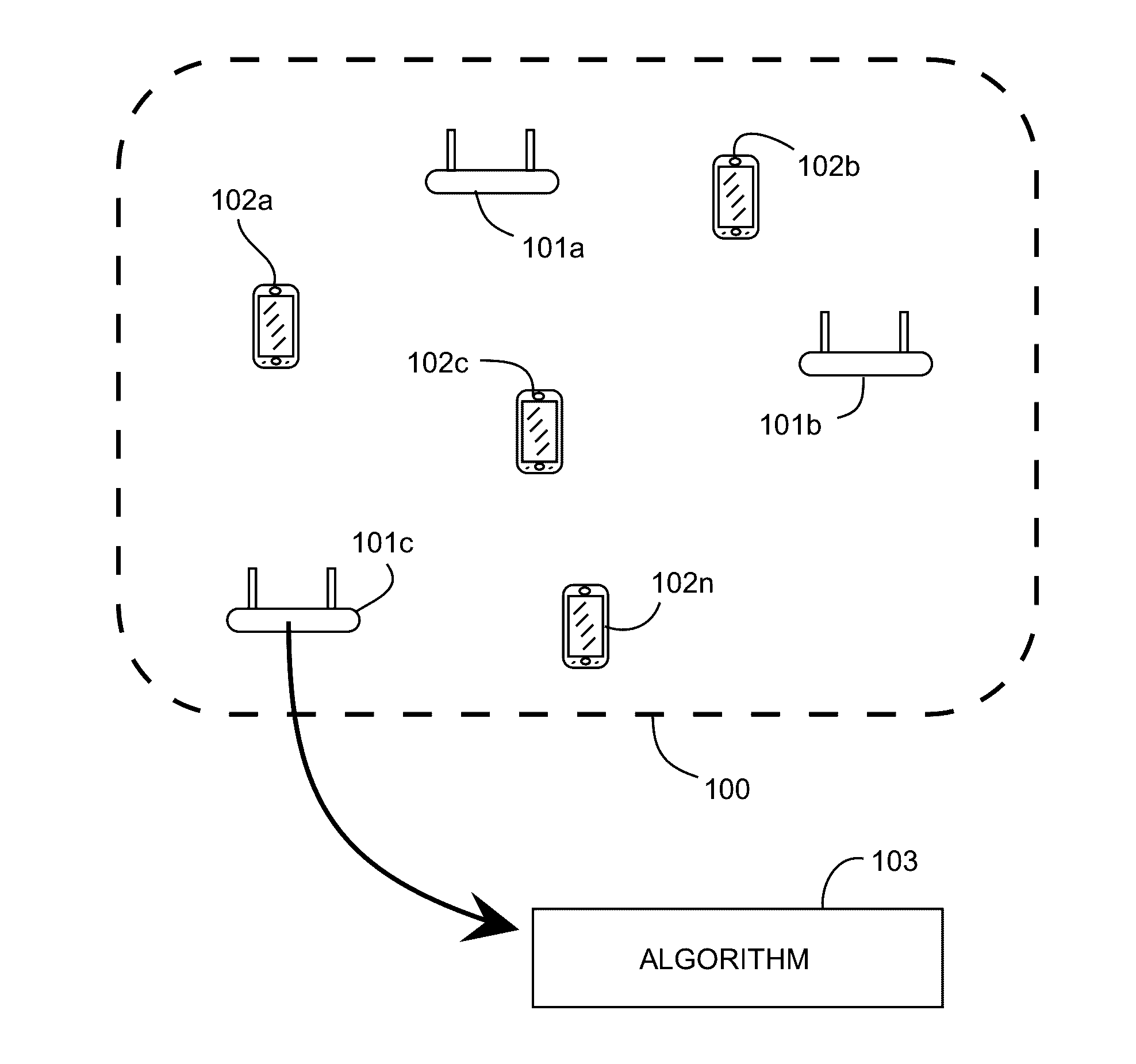
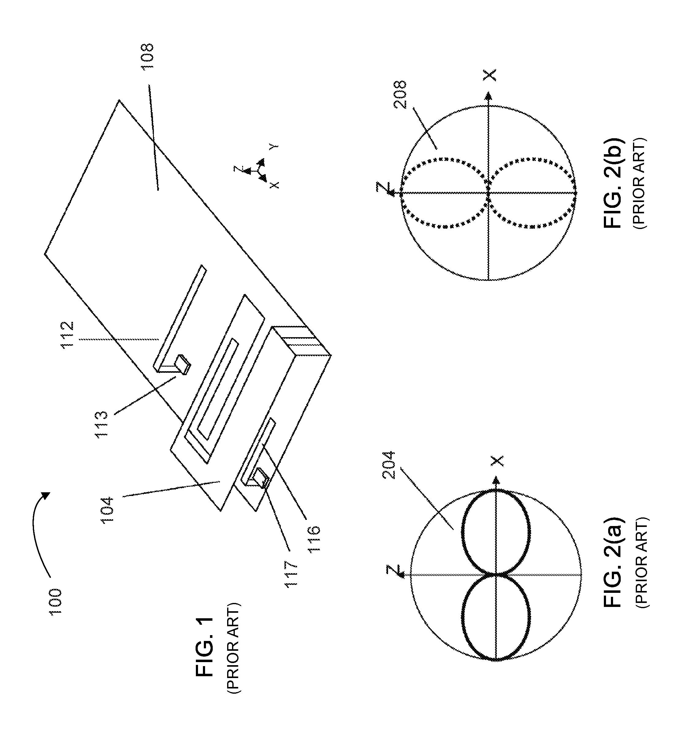
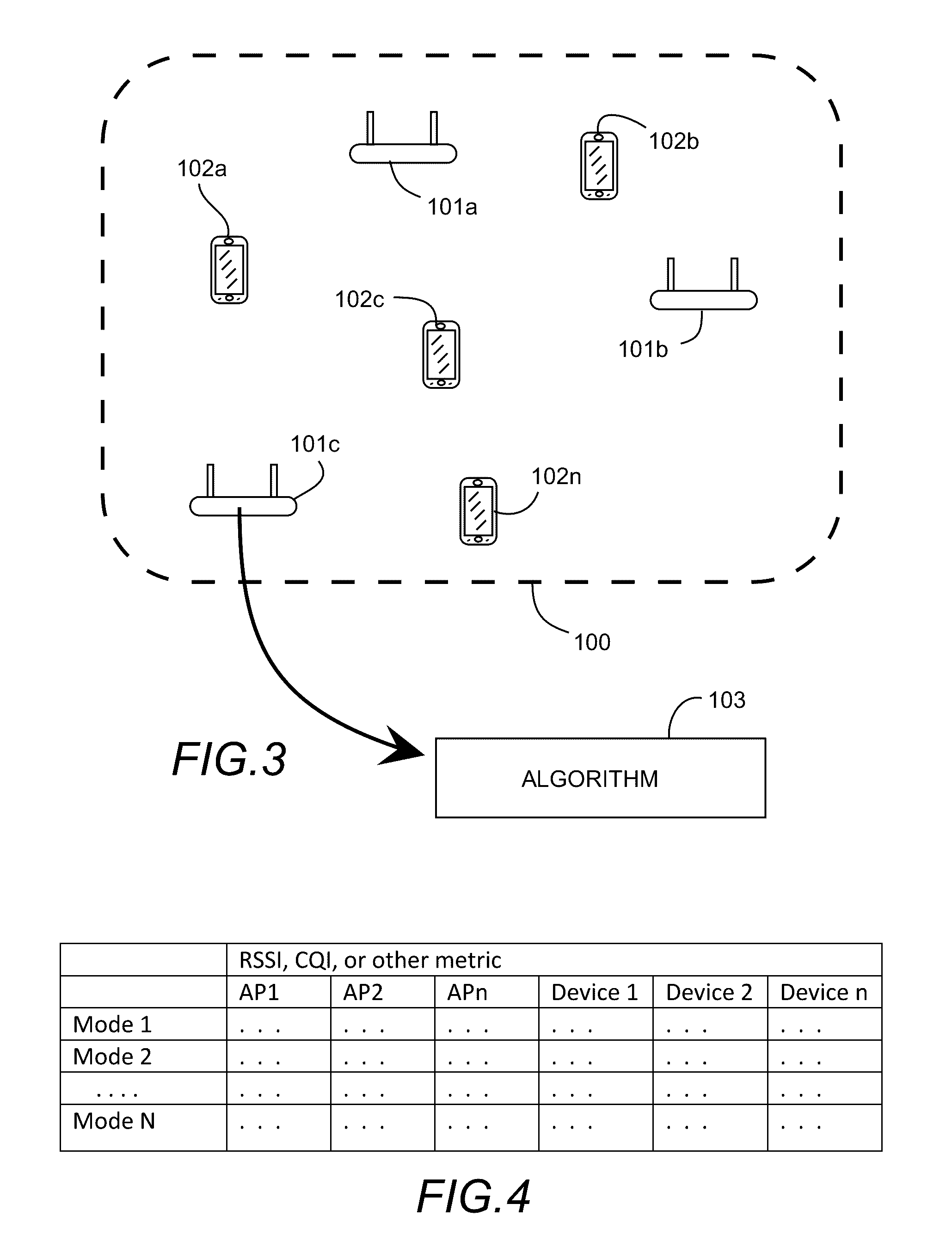
[0038]Herein described is a communication network where beam steering antenna techniques are implemented in the form of modal antenna techniques at both the communication nodes and the mobile and fixed devices. A modal antenna is generally a single port antenna system capable of generating multiple radiation modes, wherein the radiation modes are de-correlated when compared to e...


PUM


Abstract

A communication network is optimized using modal antenna techniques, wherein a plurality of communication nodes are synchronized with each other along with mobile and fixed wireless communication devices which comprise the user base. With one or more of the communication nodes and wireless communication devices including at least one respective modal antenna, the network is adapted for dynamic optimization of communication links amongst the wireless users. Node to user throughput, node to node throughput, as well as interference characteristics among the nodes and wireless users are each optimized as a network system to increase communication system network capacity and reliability. The multiple radiation patterns provided by the modal antennas provide a parametric for network-level synchronization to improve communication system performance.

Description

CROSS-REFERENCE TO RELATED APPLICATIONS[0001]This application claims benefit of priority with U.S. Provisional Ser. No. 61 / 955,163, filed Mar. 18, 2014, titled “MODAL ANTENNA BASED COMMUNICATION SYSTEM”; the contents of which are hereby incorporated by reference.BACKGROUND[0002]1. Field of the Invention[0003]This invention relates generally to the field of wireless communication; and more particularly, to communication networks and improvements afforded to these networks when beam steering techniques via modal antenna systems are used on both communication nodes and wireless subscribers to increase system capacity and mitigate interference therebetween.[0004]2. Description of the Related Art[0005]In the field of wireless communications, a recent technological advancement includes the advent of multi-mode active antennas, or “modal antennas”. A modal antenna is a single port antenna capable of being actively reconfigured between a plurality of antenna modes, wherein the modal antenna...

Claims


Application Information

Patent Timeline
Patent Type & Authority Patents(United States)
IPC IPC(8): H04B1/00H01Q1/24H01Q3/44H01Q9/42H04B7/155H04W40/12H04W72/04H04B15/00H04B7/08
CPCH04B7/082H01Q1/243H01Q3/44H01Q9/42H04B7/1555H04W40/12H04W72/046H04B7/10
Inventor DESCLOS, LAURENTSHAMBLIN, JEFFREY
Owner KYOCERA AVX COMPONENTS (SAN DIEGO) INC
Why Eureka
Try Eureka