Remote control of light source

a remote control and light source technology, applied in the field of remote control units, can solve the problems of inability to accurately locate some or even all individual lighting elements, difficulty in carrying along individual remote control units for each light, and inability to scale well on hard-wired wall-mounted control units

Active Publication Date: 2016-10-25
KONINK PHILIPS ELECTRONICS NV
View PDF12 Cites 1 Cited by
  • Summary
  • Abstract
  • Description
  • Claims
  • Application Information

AI Technical Summary

Benefits of technology

[0010]It is an object of the present invention to overcome at least one of these problems, and to provide a remote control unit and a method for controlling a set of light sources that are less time consuming, more flexible and scalable, without being complex or error prone.
[0011]The inventors of the enclosed embodiments have realized that advances in connectivity may enable seamless interoperability between the lighting infrastructure and interactive devices, such as mobile telephones, tablet computers, electronic photo frames, and television screens. This could enable ways for creating lighting settings and lighting scene using the mobile telephone, tablet computer, electronic photo frame, or television screen as a remote control unit.
[0012]It is therefore a particular object of the present invention to propose an easy way for operators (end-users) to perform settings to lighting elements by indicating relations between selected areas in an image and available light sources.
[0015]Preferably this allows for control of light sources which do not have any localization means and where the user is enabled to select colors of an image as a basis for determining color values of the light sources.
[0016]Preferably this enables for an easy way for operators (end-users) to manually perform the mapping between light sources and color information by manually indicating relations between selected areas in an image picture and available light sources.

Problems solved by technology

For example, carrying along an individual remote control unit for each light can be a tedious and error prone process.
For example, a hard-wired wall-mounted control unit does not scale well.
In relation to the third example, one problem may be that the location of some or even all individual lighting elements may be unknown.
As a result thereof it could be difficult to make a proper mapping from image to lighting elements.

Method used


Image

  • Remote control of light source
  • Remote control of light source
  • Remote control of light source

Examples


Embodiment Construction

[0028]The below embodiments are provided by way of example so that this disclosure will be thorough and complete, and will fully convey the scope of the invention to those skilled in the art. Like numbers refer to like elements throughout.

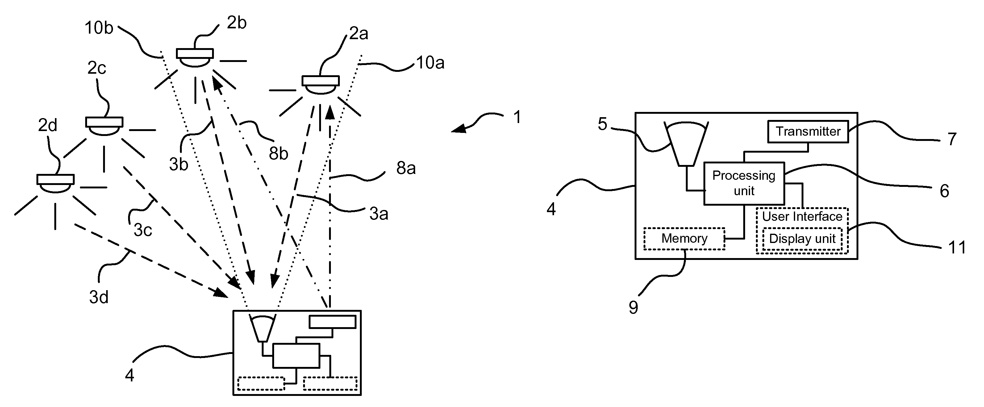
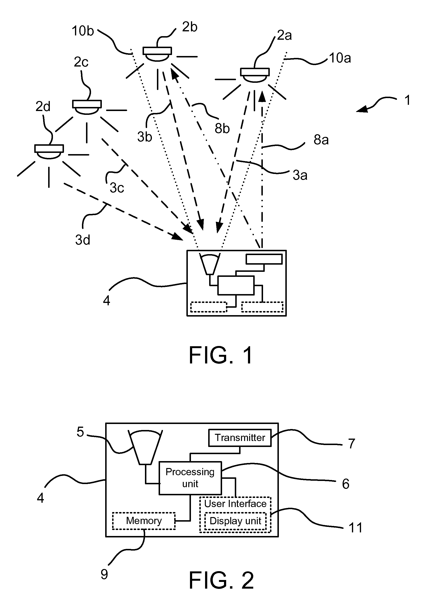
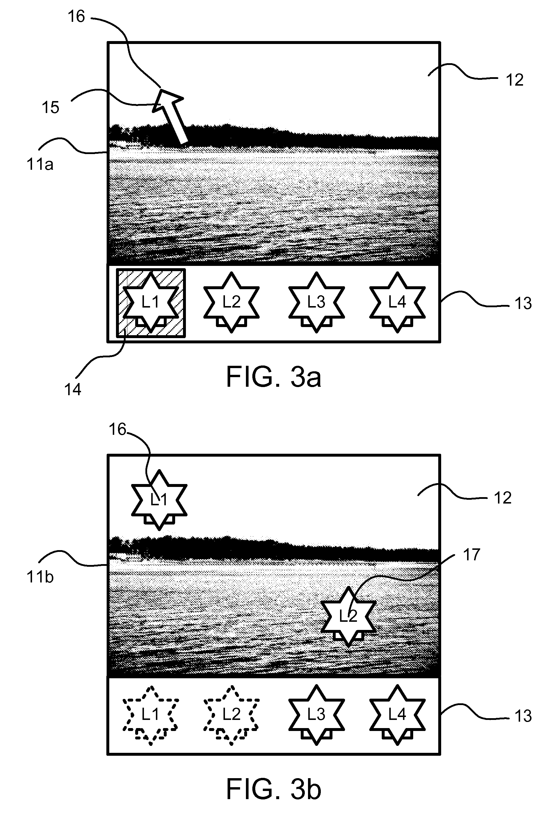
[0029]One problem with the prior art is, as mentioned above, that the location of individual lighting elements often is unknown. This makes it difficult to make a proper mapping from an image to lighting elements. For that reason, the proposed embodiments are related to means for user interaction, which gives operators (end-users) the possibility to make a mapping between colors in an electronic image (segment) and specific light sources. As will be further elaborated below, such means could be realized by using graphical representations (such as image icons) of available light sources being displayed on top of an image, thereby enabling the operator (end-user) to move, drag or otherwise manipulate the graphical representation towards particular po...


PUM


Abstract

A lighting system comprises a set of light sources and a remote control unit. The remote control unit comprises a user interface through which a user may identify an area in an image and a light source. The identified image area is linked with the light source and color information of the identified image area is transmitted to the light source. The light source is thereby enabled to adapt its light output to the color information. A user is thereby enabled to pick the color to be outputted by a light source by selecting an area in an image displayed on the remote control unit. The remote control unit may be part of a mobile telephone, a tablet computer, an electronic photo frame, or a television screen.

Description

CROSS-REFERENCE TO PRIOR APPLICATIONS[0001]This application is the U.S. National Phase application under 35 U.S.C. §371 of International Application No. PCT / IB13 / 050782, filed on Jan. 30, 2013, which claims the benefit of U.S. Provisional Patent Application No. 61 / 597,858, filed on Feb. 13, 2012. These applications are hereby incorporated by reference herein.FIELD OF THE INVENTION[0002]The present invention relates to the field of lighting systems and in particular to a remote control unit and a method for controlling a set of light sources in the lighting system.BACKGROUND OF THE INVENTION[0003]The advent of integrated lighting installations, consisting of an ever growing number of individually controllable light sources, luminaires, lighting arrangements and the like with advanced rendering capabilities, may be regarded as transforming lighting systems for both professional and consumer markets. This brings a need for an intuitive control capable of fully exploiting the rendering ...

Claims


Application Information

Patent Timeline
Patent Type & Authority Patents(United States)
IPC IPC(8): H05B37/02
CPCH05B37/0245H05B37/0272H05B47/19H05B47/10H05B47/195H05B47/175
Inventor VAN DE SLUIS, BARTEL MARINUSCUPPEN, ROEL PETER GEERT
Owner KONINK PHILIPS ELECTRONICS NV
Why Eureka
Try Eureka