Coronary artery catheter and engaging method therefor

a technology of coronary artery and catheter body, which is applied in the direction of guide needles, medical devices, other medical devices, etc., can solve the problems of imposing a heavy burden on the patient, excessive backup force to be generated, and insufficient backup force owing to bending, etc., to achieve excessive insertion of catheter body into coronary artery, and excessive backup force is restrained

Active Publication Date: 2016-11-01
TERUMO KK
View PDF11 Cites 14 Cited by
  • Summary
  • Abstract
  • Description
  • Claims
  • Application Information

AI Technical Summary

Benefits of technology

[0008]In view of this, a method of introducing a coronary artery catheter from an artery of an arm, particularly a brachial artery or a radial artery, has been proposed in recent years. When the coronary artery catheter is introduced from an artery of an arm, the compression time and recovery time after the operation can be shortened, so that the burden on the patient can be lessened.
[0015]The coronary artery catheter may be so configured that when the coronary artery catheter is introduced through an artery of an arm and the distalmost section is engaged with the coronary ostium, the distalmost section extends from a position, on an aortic valve side relative to the coronary ostium, in the ascending aorta toward the coronary ostium, and an axis of the distalmost section is inclined relative to an axis of the coronary ostium; the distalmost section and part of the second curved section are curved in a same first direction; part of the second curved section makes linear contact with an inner wall of the ascending aorta opposite to the coronary ostium; the intermediate straight section is disposed inside the ascending aorta and inside the brachiocephalic trunk in a state where its distal portion is curved in the first direction whereas its proximal portion is curved in a second direction opposite to the first direction; the first curved section is disposed inside the brachiocephalic trunk in a state of being curved in the second direction; and the proximal straight section is disposed inside the brachiocephalic trunk or inside a right subclavian artery in a state of being curved in the second direction, and at least part thereof makes linear contact with an inner wall of the brachiocephalic trunk or an inner wall of the right subclavian artery. This configuration ensures that the catheter body is favorably supported in the arteries by the functions of the distalmost section which is engaged with the coronary ostium, the second curved section which is engaged with the inner wall of the ascending aorta, and the proximal straight section which is engaged with the inner wall of the brachiocephalic trunk or the right subclavian artery. In addition, since the distalmost section extends from the position, on the aortic valve side relative to the coronary ostium, in the ascending aorta toward the coronary ostium and the axis of the distalmost section is inclined relative to the axis of the coronary ostium, a force for clamping something between the distalmost section and the second curved section is generated in the vicinity of the coronary ostium. Due to this force, the distalmost section will hardly be disengaged from the coronary ostium. In addition, since the intermediate straight section has an inflection point, generation of an excessive backup force is restrained. Moreover, the axis of the distalmost section is inclined relative to the axis of the coronary ostium. Consequently, excessive insertion of the catheter body into the coronary artery is restrained.
[0016]The coronary artery catheter may be so configured that when the coronary artery catheter is introduced through an artery of an arm and the distalmost section is engaged with the coronary ostium, the distalmost section makes linear contact with an inner wall of the coronary artery; at least part of the second curved section makes linear contact with the inner wall of the ascending aorta opposite to the coronary ostium while being curved in the first direction; the intermediate straight section is disposed inside the ascending aorta and inside the brachiocephalic trunk in a state of being curved in the second direction opposite to the first direction; the first curved section is disposed inside the brachiocephalic trunk in a state of being curved in the second direction; and the proximal straight section is disposed inside the brachiocephalic trunk or inside the right subclavian artery in a state of being curved in the second direction, and at least part thereof makes linear contact with the inner wall of the brachiocephalic trunk or the inner wall of the right subclavian artery. This configuration ensures that the catheter body is favorably supported in the arteries by the functions of the distalmost section which is inserted in and engaged with the coronary artery, the second curved section which is engaged with the inner wall of the ascending aorta, and the proximal straight section which is engaged with the inner wall of the brachiocephalic trunk or the right subclavian artery. Besides, since the intermediate straight section being originally straight is bent, generation of an excessive backup force is restrained. Consequently, excessive insertion of the catheter body into the coronary artery is restrained.

Problems solved by technology

Thus, this approach imposes a heavy burden on the patient.
Although this bending causes generation of a backup force, the backup force owing to the bending is not displayed sufficiently, since the bent section curved in the direction opposite to the bending is present on the distal side relative to the part of the bending.
This may cause an excessive backup force to be generated.

Method used


Image

  • Coronary artery catheter and engaging method therefor
  • Coronary artery catheter and engaging method therefor
  • Coronary artery catheter and engaging method therefor

Examples


Embodiment Construction

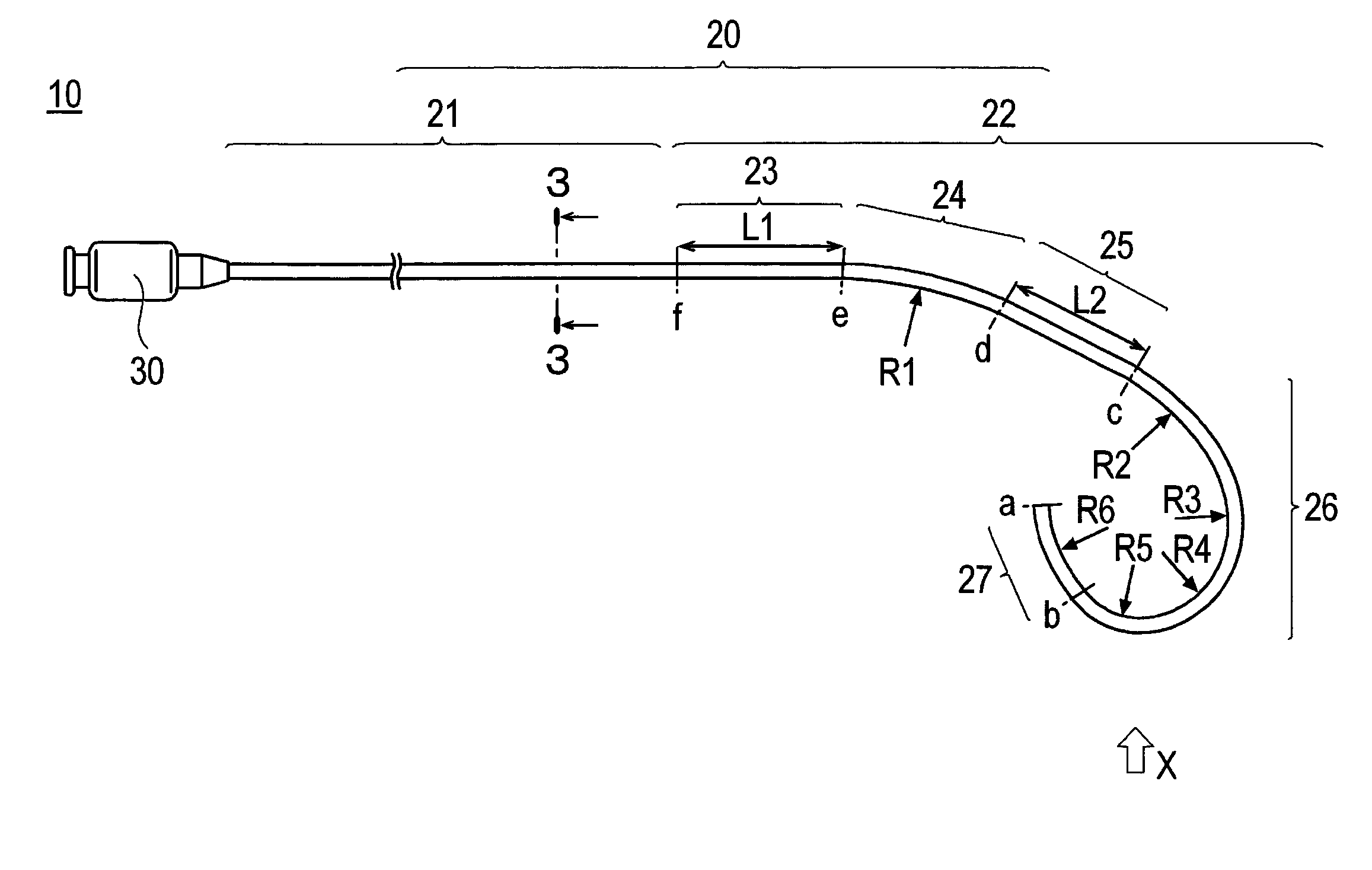
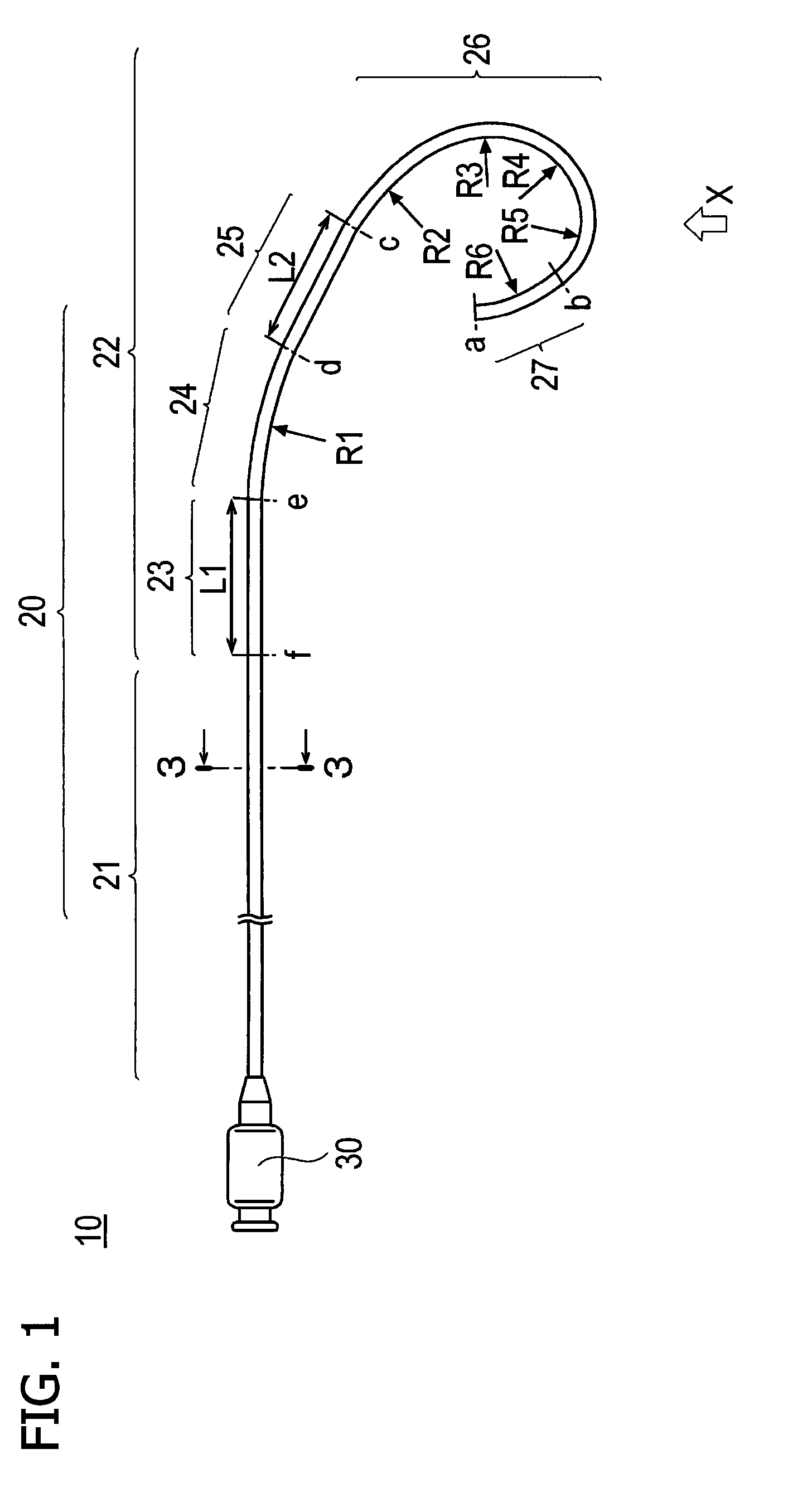
[0028]Now, an embodiment of the present invention will be described below referring to the drawings. Incidentally, dimensional ratios in the drawings may be exaggerated, for convenience of description, so as to be different from actual ratios. With respect to a coronary artery catheter herein, the side of insertion into a lumen will be referred to as “distal” or “distal side,” and the side of operation by hand will be referred to as “proximal” or “proximal side.”

[0029]A coronary artery catheter 10 according to an embodiment of the present invention (hereafter referred also to simply as “catheter 10”) is adapted for introducing its distal end from an artery of a left or right arm (particularly, an artery of a right arm) into a left or right coronary ostium (particularly, a left coronary ostium 102—see FIG. 5). Incidentally, the coronary artery catheter 10 according to the present embodiment may have its distal end introduced from a femoral artery into the left or right coronary ostiu...


PUM


Abstract

A coronary artery catheter adapted for introducing its distal end into a coronary ostium through an artery includes a catheter body with a lumen formed therein. The catheter body in a natural state includes: a proximal straight section extending distally from a proximal end of the catheter body; a first curved section extending distally from the proximal straight section while being curved; an intermediate straight section extending distally from the first curved section; a second curved section extending distally from the intermediate straight section while being curved; and a distalmost section extending from the second curved section to a distal end of the catheter body. The first curved section and the second curved section, when projected onto a plane on which the first curved section and the intermediate straight section are present, curve in the same direction.

Description

CROSS-REFERENCE TO RELATED APPLICATION[0001]This application claims priority to Japanese Patent Application No. 2012-161035 filed on Jul. 20, 2012, the entire content of which is incorporated herein by reference.TECHNICAL FIELD[0002]The present invention relates to a coronary artery catheter for use in therapy or imaging of the heart or the surroundings thereof and to an engaging method for the coronary artery catheter.BACKGROUND[0003]Conventionally, a coronary angiography catheter has been used to supply a radiopaque material (contrast agent) into a coronary artery for imaging the coronary artery.[0004]In addition, treatments of peripheral regions of a patient by use of a catheter or catheters have been widely practiced. One example of such treatments is the percutaneous transluminal coronary angioplasty (PTCA) as a treatment of ischemic cardiopathy based on the use of a therapeutic catheter equipped with an inflatable balloon. In such a treatment, in order to insert the therapeuti...

Claims


Application Information

Patent Timeline
Patent Type & Authority Patents(United States)
IPC IPC(8): A61M25/00A61M25/06
CPCA61M25/00A61M25/005A61M25/0041A61M2025/0681A61M2210/125
Inventor FUKUOKA, TETSUYAOTAKE, YUYAUEDA, MARIKO
Owner TERUMO KK
Why Eureka
Try Eureka