Sheet groove cutter capable of operation without use of ruler

a technology of floor sheet and groove cutter, which is applied in the field of floor sheet groove cutter, can solve the problems of difficult to press directly the heat melted welding rod into the narrow gap, is practically impossible to bind each floor sheet tightly by using such methods, and takes a huge amount of time and effort, and achieves the effect of beautiful concave groove, easy and accurate operation, and easy and accurate operation

Active Publication Date: 2016-11-01
IIMORI IKUMI +1
View PDF18 Cites 0 Cited by
  • Summary
  • Abstract
  • Description
  • Claims
  • Application Information

AI Technical Summary

Benefits of technology

[0018]By using the groove cutter of the present invention, a concave groove can be easily and accurately obtained at the seam existing between the sheets without using a ruler or the like, and the concave groove also can be easily and accurately obtained along the seam and at the seam, which is created between the sheets attached to base sheets having small surface irregularities or formed as curved seam from a design-centric viewpoint, although it was difficult in these cases to obtain the concave groove beautifully even though the ruler or the like was used. In addition, in cases of cutting further groove inside the groove cut first, by means of the present invention, the working efficiency of grooving welding operation can be remarkably improved and adjacent sheets are bound much stronger each other than ever, since the melted welding rod pressed into the groove can hardly be detached from the groove formed at the seam of the floor sheets.

Problems solved by technology

In this case, since the floor sheets are laid so closely each other from the beginning, it is difficult to press directly the heat melted welding rod into the narrow gap, which exists at the seam, from the top of the seam.
Therefore, it is practically impossible to bind each floor sheet tightly by using such method.
According to this method, except when it is difficult to cut a groove having desired depth since sheets are thin or hard, it is possible to bind sheets tightly to some extent.
However, when a floor space is larger and a seam is longer in length, there is a disadvantage that it takes an immense amount of time and effort and also an operating cost becomes huge.
However, since the distance between the support points and a grip is long, there are disadvantages that not only the stability is limited but also a tool itself is easy to break.
With regard to this device, there was a disadvantage that this device causes a risk to cut off the part other than the seam of the floor in the process of operation, since the front roller, which is the seam guide, is apt to run off from the seam.
Furthermore, there were other disadvantages that the device cannot follow the seam sufficiently, since the rear roller, even though a width of it is wider than that of the above front roller, is not always stable in the wide cut groove which is formed by a blade equipped just behind the roller provided at front of the device, and also the device cannot sufficiently correspond to surface irregularities of floor.
And also, there was one more disadvantage that, the rear roller, and if the second blade is provided at the rear, the second blade should also be detached when a curved groove is formed, which is a troublesome operation.

Method used


Image

  • Sheet groove cutter capable of operation without use of ruler
  • Sheet groove cutter capable of operation without use of ruler
  • Sheet groove cutter capable of operation without use of ruler

Examples


Embodiment Construction

[0034]Hereafter, the present invention is explained according to Examples, however, the present invention is not limited by these Examples. In this regard, the groove cutter for floor sheets of the present invention will be described and explained simply as “a tool” in the present specification.

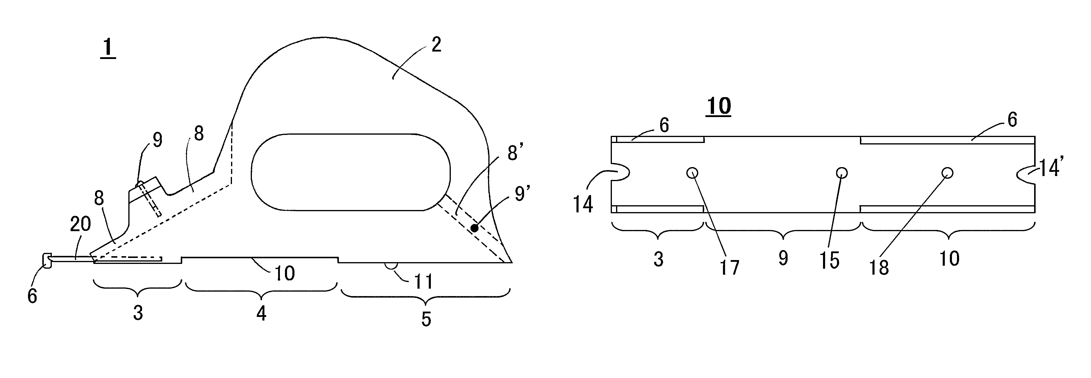
[0035]FIG. 6 is an example of side view of the groove cutters of the present invention for the case of manufacturing the body integrally except the bottom and the movable portions. In the views, numeral 1 is the tool body of the present invention, 2 is the grip, 3 is the front part, 4 is the middle part, 5 is the rear part, 6 is the thin guide plate guiding the seam of floor sheets, 7 is the cutting blade for the U-shaped or V-shaped concave groove, 8 and 8′ are groove-like or tube-like spaces set for equipping the groove-cutting blade, 9 and 9′ are screw bolts for detaching the groove-cutting blade or adjusting a position of the groove-cutting blade, 10 is the bottom part covering the whole ...


PUM

PropertyMeasurementUnit
depthaaaaaaaaaa
widthaaaaaaaaaa
thicknessaaaaaaaaaa

Abstract

A groove cutter for floor sheets capable of being operated without using a ruler and can cut a seam, which is created when sheets are laid sequentially on the surface of floor base with an adhesive agent, so that a groove formed along the seam can bridge over both adjacent sheets, comprising a front part, a middle part, a rear part, wherein the front part has a thin guide plate, which is to be inserted into the seam and guides the tool along the seam when pushing the tool forward, at the front end, and at least one blade to cut a concave groove at the seam part of the sheet, which is provided behind the guide plate so as to be detachable, and a stabilizing member provided at the rear part, which is to be inserted into the concave groove, to stabilize a direction of movement along the seam.

Description

TECHNICAL FIELD[0001]The present invention relates to a groove cutter for floor sheets which can form a concave groove, necessary for bonding tightly the adjacent floor sheets by use of a welding rod, on the seam formed by the adjacent floor sheets, and in particular relates to a groove cutter for floor sheets wherein a concave groove at a seam, which is formed bridging over the floor sheets, can be formed rapidly and accurately without using a ruler.BACKGROUND OF THE INVENTION[0002]Generally, when floor sheets are bonded to a base sheet of floor, in order to bind a seam of individual floor sheets tightly, a method of pouring a heat melted welding rod into the said seam is used. In this case, since the floor sheets are laid so closely each other from the beginning, it is difficult to press directly the heat melted welding rod into the narrow gap, which exists at the seam, from the top of the seam. Therefore, even if the welding rod had been pressed into the gap, the heat melted weld...

Claims


Application Information

Patent Timeline
Patent Type & Authority Patents(United States)
IPC IPC(8): B26B29/06B27B27/00B26D3/06E04F21/165B29C65/00B29C65/42B29L31/30
CPCB26D3/065E04F21/165E04F21/1652B29C65/42B29C66/02241B29C66/1142B29C66/43B29L2031/3017Y10T83/0304E04F15/02016E04F15/02033E04F15/0215E04F15/06E04F21/20
Inventor IIMORI, IKUMIAZUMA, YOSHIHARU
Owner IIMORI IKUMI
Why Eureka
Try Eureka