Resonant frequency divider design methodology for dynamic frequency scaling

Active Publication Date: 2016-11-01
DREXEL UNIV
View PDF5 Cites 2 Cited by
  • Summary
  • Abstract
  • Description
  • Claims
  • Application Information

AI Technical Summary

Problems solved by technology

1) The power savings and the stability of the resonant rotary clocking are directly proportional to its operating frequency; thus, lower frequency implementations of rotary clocking are often inefficient. For instance, when the resonant clocking implementation on AMD Piledriver chip is used at high frequencies, and the clock network is multiplexed off to be driven by a

Method used


Image

  • Resonant frequency divider design methodology for dynamic frequency scaling
  • Resonant frequency divider design methodology for dynamic frequency scaling
  • Resonant frequency divider design methodology for dynamic frequency scaling

Examples


Embodiment Construction

I. Introduction

[0015]The circuit and method described herein may add value to the integration of resonant clocking to system architecture design through enabling DFS.

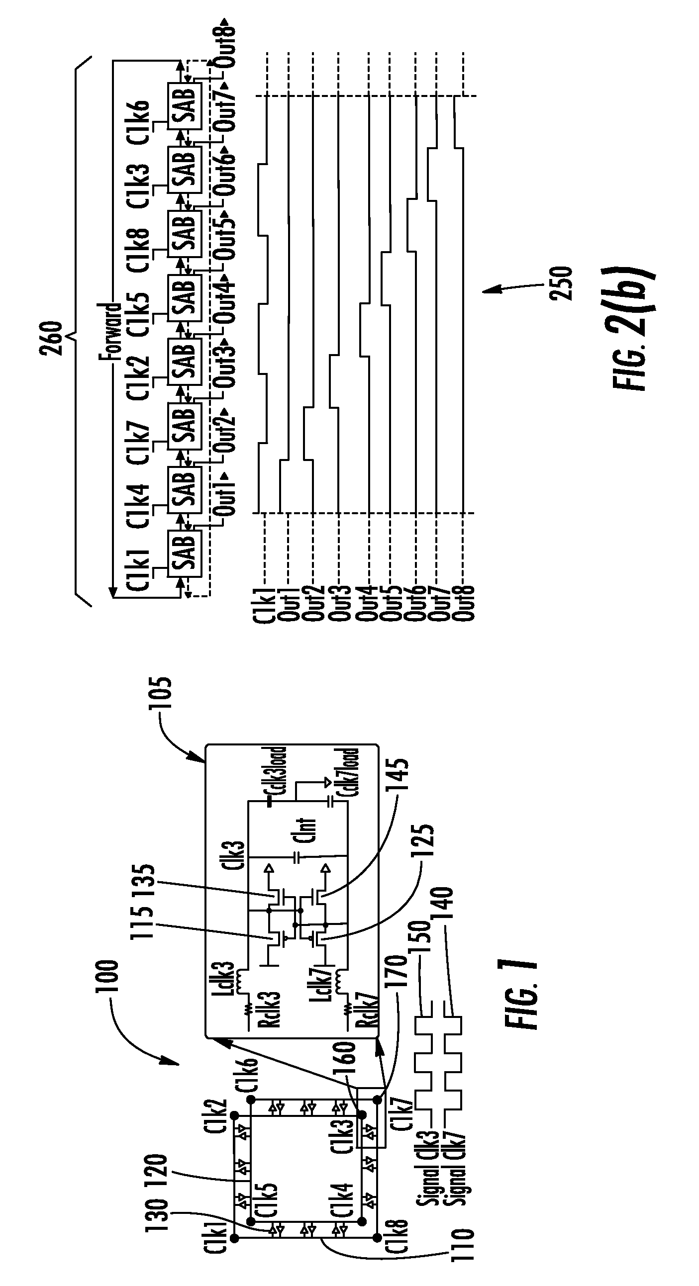
[0016]As shown in FIG. 1, a rotary traveling wave oscillator (RTWO) 100 comprises two differential transmission lines 110, 120 with cross-connections between them to form a Mobius loop. Anti-parallel inverter pairs 130 may be connected between these two transmission lines 110, 120, which are used to overcome the energy loss during the signal propagation. The traveling signals 140, 150 along the transmission lines 110, 120 of the RTWO provide multiple phase signals for sampling, all of which may maintain a duty cycle of 50%.

[0017]If point Clk3160 is defined with clock signal delay t=0 and phase θ=0, the clock signal travels along the RTWO 100 and reaches point Clk7170 with phase θ=π and back to Clk3160 with phase θ=2π. The phase delay is evenly distributed along the RTWO transmission line in the wave propagating directio...


PUM


Abstract

A dynamic rotary traveling wave oscillator circuit includes plurality of multi-output spot-advancing blocks (MOSABs) forming a main-loop and a plurality of multi-input spot-advancing blocks (MISABs) forming a sub-loop. Depending on a desired division ratio, a connection connects blocks on the MOSABs and MISABs to create the desired division ratio.

Description

STATEMENT REGARDING FEDERALLY SPONSORED RESEARCH[0001]The United States Government may have certain rights in this invention pursuant to National Science Foundation Contract award number #0845270.BACKGROUND[0002]A dynamic frequency scaling (DFS) scheme based on resonant rotary clocking may address certain needs:[0003]1) The power savings and the stability of the resonant rotary clocking are directly proportional to its operating frequency; thus, lower frequency implementations of rotary clocking are often inefficient. For instance, when the resonant clocking implementation on AMD Piledriver chip is used at high frequencies, and the clock network is multiplexed off to be driven by a non-resonant clock source for lower frequency modes.[0004]2) While a frequency division circuitry exists for resonant rotary clocking (e.g. not for coupled LC oscillator-based type that is used but for RTWO), the rotary clock frequency divider is a static divider and cannot perform dynamic frequency scali...

Claims


Application Information

Patent Timeline
IPC IPC(8): H03K21/02H03K21/10H03B27/00H03K27/00H03K21/08H03K23/54H03K3/03H03B5/18
CPCH03K3/0315H03B5/18H03B27/00H03K21/02H03K21/08H03K21/10H03K23/54H03K27/00
Inventor TASKIN, BARISTENG, YING
Owner DREXEL UNIV
Why Eureka
Try Eureka