
Low noise fractional divider using a multiphase oscillator

a fractional divider and multiphase technology, applied in the field of frequency synthesis, can solve the problems of reducing the signal-to-noise ratio seriously, reducing the spectral purity compared to the ideal, and not supporting high frequency operation of the synthesizer, so as to achieve the effect of facilitating integrated circuit fabrication and greater spectral purity

Active Publication Date: 2012-10-02
ANALOG DEVICES INC
View PDF6 Cites 1 Cited by
  • Summary
  • Abstract
  • Description
  • Claims
  • Application Information

AI Technical Summary

Benefits of technology

The present invention is a frequency synthesizer circuit that includes a multi-phase oscillator, loop filter, control circuit, selecting means, dividing means, synchronizer, phase-frequency detector, and delta sigma modulator. The circuit can generate multiple phases at a controllable frequency with high spectral purity, making it useful in a wider range of applications. It also uses digital circuitry to select the phases, making it suitable for integrated circuit fabrication. The technical effects of the invention are improved output frequency purity and increased flexibility in applications and fabrication methods.

Problems solved by technology

Of course, no such oscillator exists; a real oscillator has spectral power distributed about the nominal oscillator frequency, which reduces its spectral purity compared to the ideal.
This spectral power causes the introduction of oscillator noise into the down-converted signal, which seriously reduces the signal-to-noise ratio of the signal when there are large unwanted signals near the desired radio frequency signal.
The table look-up synthesizer does not support high frequency operation and the direct synthesizer has a problem with spectral purity.
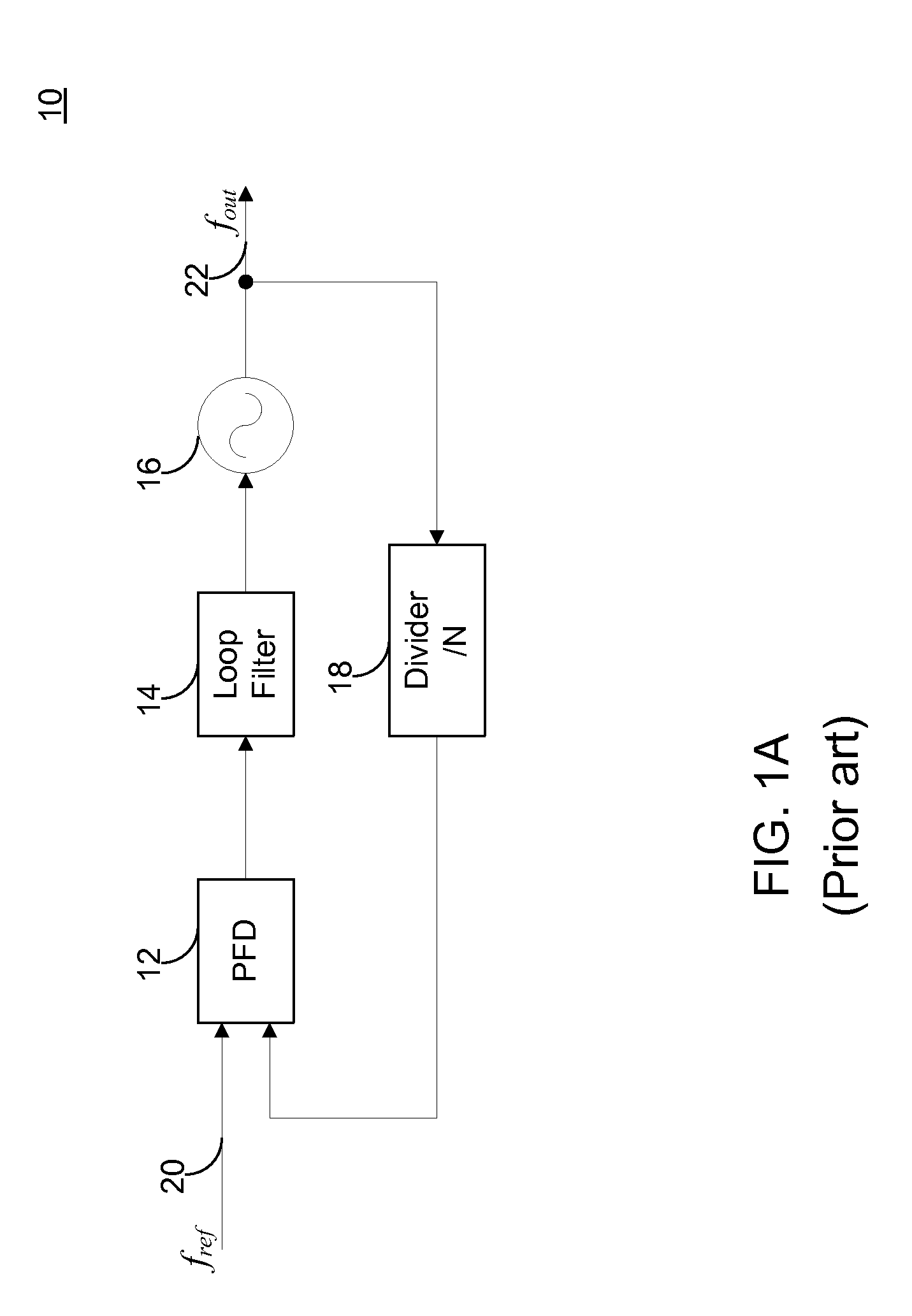
One problem with the configuration of FIG. 1A is that it lacks flexibility.
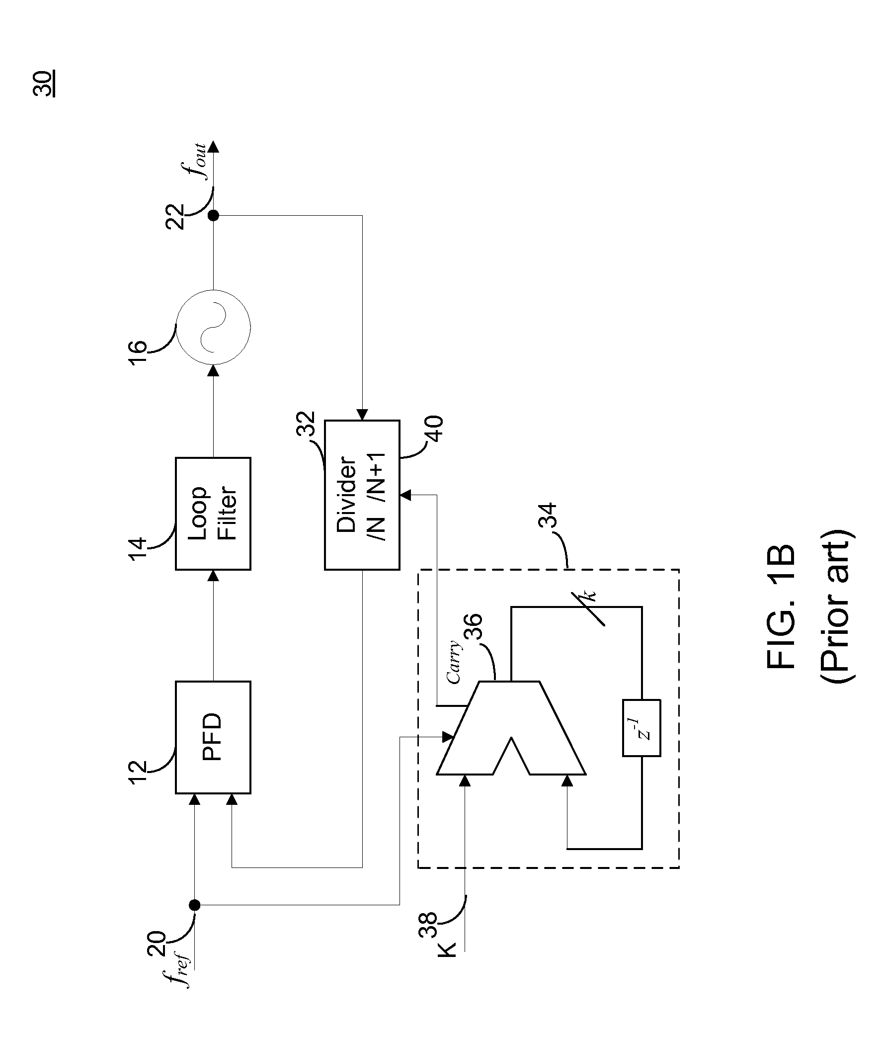
However, the fractional-N configuration still has a drawback, which is that the periodic selection of the integer N or N+1 creates noise in the synthesized frequency.
These spikes in the spectrum are very undesirable and make this form of fractional divider unacceptable for modern communications systems.

Method used


Image

  • Low noise fractional divider using a multiphase oscillator
  • Low noise fractional divider using a multiphase oscillator
  • Low noise fractional divider using a multiphase oscillator

Examples


Embodiment Construction

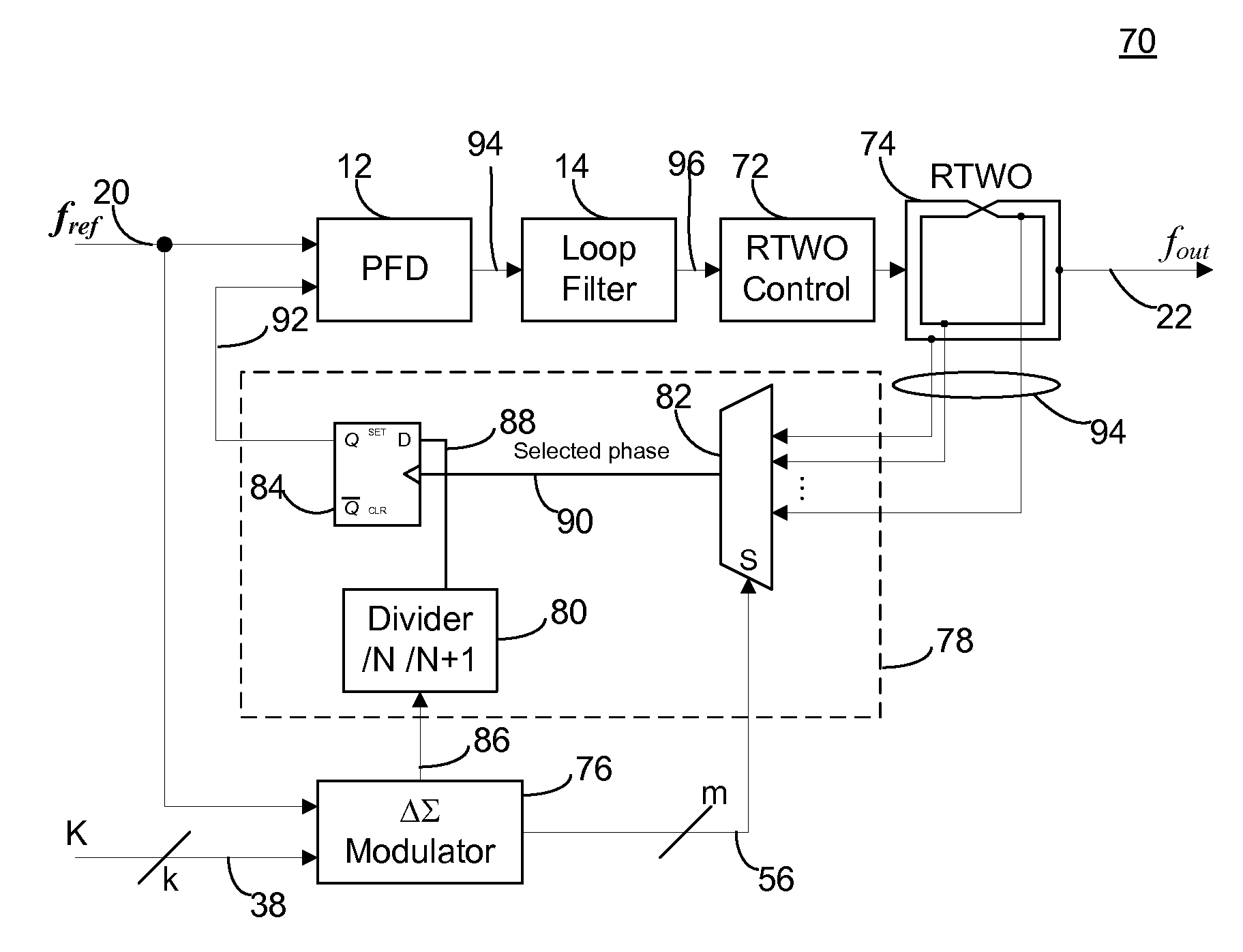
[0027]Even though a higher order ΔΣ modulator addresses one source of the noise, i.e., the frequency shift generated by the shifts in the divider ratio, another source of noise remains, which is the phase shift that accompanies the shift in divider ratios. The present invention addresses this source of noise. By utilizing the many phases available from a multi-phase oscillator such as a rotary traveling wave oscillator (RTWO), the present invention dramatically reduces the noise generated in a fractional-N synthesizer. (A rotary traveling wave oscillator is disclosed in U.S. Pat. No. 6,556,089, which is incorporated by reference in its entirety into this application.) Using only two divider ratios N and N+1, a multibit ΔΣ modulator output selects one of the many available phases of the RTWO for input to a synchronizer whose output drives the PFD. FIG. 3A shows this arrangement. For an order O modulator, the noise improvement is 20·log10(2O). In a 3rd-order modulator, the noise impro...


PUM


Abstract

A frequency synthesis circuit is disclosed. The circuit includes a phase-locked loop and multi-phase oscillator such as a rotary traveling wave oscillator (RTWO). The oscillator provides a plurality of phases that are applied to a selection circuit. The selection circuit, in response to the output of a delta-sigma modulator, selects one of the phases of the multi-phase oscillator to minimize phase shift noise when the divider ratio in the loop changes, thereby eliminating a source of noise that contaminates the synthesized frequency. This permits the use of the frequency synthesis in applications requiring a high degree of spectral purity.

Description

CROSS-REFERENCE TO RELATED APPLICATIONSField of the Invention[0001]The present invention relates generally to frequency synthesis and more particularly to frequency synthesis using a PLL.DESCRIPTION OF THE RELATED ART[0002]Wireless communications systems usually require a local oscillator to generate one or more frequencies for down-conversion of a received radio frequency signal. Ideally, the spectrum of the local oscillator is a single spectral line at the nominal frequency of the oscillator. Of course, no such oscillator exists; a real oscillator has spectral power distributed about the nominal oscillator frequency, which reduces its spectral purity compared to the ideal. This spectral power causes the introduction of oscillator noise into the down-converted signal, which seriously reduces the signal-to-noise ratio of the signal when there are large unwanted signals near the desired radio frequency signal. Therefore, it is a design goal to minimize the spectral power about the no...

Claims


Application Information

Patent Timeline
Patent Type & Authority Patents(United States)
IPC IPC(8): H03L7/06
CPCH03L7/0995H03L7/1976H03B5/1852
Inventor BECCUE, STEPHEN MARK
Owner ANALOG DEVICES INC
Learn More