Steel strip stabilization device

a stabilizing device and steel strip technology, applied in the direction of filament handling, transportation and packaging, coating, etc., can solve the problems of quality defects, plating failure, plating failure, etc., to improve the plating quality of steel strip, reduce the deviation of plating, and improve the shape correction and/or vibration damping of plated steel strip

Active Publication Date: 2016-11-08
POHANG IRON & STEEL CO LTD
View PDF20 Cites 0 Cited by
  • Summary
  • Abstract
  • Description
  • Claims
  • Application Information

AI Technical Summary

Benefits of technology

[0035]According to the present invention, the (electro) magnetic attraction force with respect to the steel strip may increase, and the magnetic field generating pole having various shapes may be provided to control the applied current. As a result, the shape correction and / or vibration damping in the plated steel strip may be improved, and thus, plating deviations in the steel strip may be reduced to improve the plating quality of the steel strip.
[0036]Also, the (electro) magnetic force may be used to prevent the steel strip surface defects due to the existing mechanical contact manner from occurring and also prevent contact abrasion from occurring. Thus, the steel strip stabilizing apparatus may be semipermanently used.
[0037]Furthermore, the gap (distance) between the apparatus and the steel strip may be measured by using the eddy current sensor (or the distance sensor) on the basis of the accurate and quick response characteristics to control the gap between the steel strip and the apparatus. As a result, the (electro) magnetic attraction force with respect to the steel strip may be uniformly controlled or maintained to uniformly correct the shape of the steel strip or damp vibrations of the steel strip.
[0038]Also, the apparatus support body or the magnetic field generating pole may be cooled to stably correct the shape of the steel strip or suppress vibrations of the steel strip through the (electro) magnetic attraction force.

Problems solved by technology

Here, the occurrence of the vibration in the steel strip may cause a plating deviation between the gas wiping device 120 and the steel strip, resulting in a plating failure.
On the other hand, when a curvature phenomenon (for example, a C-shaped curvature or S-shaped curvature phenomenon in which a central portion of the steel strip is recessed or curved in a width direction of the steel strip) in which the steel strip is non-uniform in shape occurs, a plating deviation in the width direction of the steel strip may occur, thus resulting in the plating failure.
However, in the case of using the mechanical touch roll, since the roll contacts the surface of the transferred plated steel strip in a state in which the molten zinc is not completely attached (dried) to the surface of the steel strip by passing through the gas wiping device, a surface roll marker may be easily formed on the surface of the plated steel strip, and particularly, foreign matters may be attached to the surface of the steel strip by using the touch roll as a medium to cause quality defects in the plated steel strip.
For example, since most steel strips for vehicles are used in vehicle frames, the surface defects in the steel strip may cause significant quality defects in products.
Also, the contact type roll may cause vibrations and noise due to abrasion thereof and also increase vibrations in the transferred plated steel strip due to unstable rotation thereof.
The related-art method for damping vibrations in the steel strip or correcting the shape of the steel strip by spraying the gas onto the steel strip may have limitations in which vibration suppression and shape correction in the steel strip are inefficient, and particularly, if the gas is sprayed onto the surface of the steel strip in the state where a plating solution is completely dried and thus is not attached to the surface of the steel strip, it may have an influence on the plating thickness of the steel strip.
Also, since the magnet block has a small unit area, the magnet block may cause stress concentration in the steel strip when the steel strip is damped in vibration and corrected in shape.
For example, in a case of a thin film having a thin thickness of about 0.6 t, a steel strip may be dented to cause surface defects of the steel strip.
Furthermore, as demand for plated steel strips used as steel strip for vehicles is rapidly increasing, large-scaled plating equipment and high-speed plating may be required.
However, the related-art steel strip stabilizing apparatus using the simple magnet block structure may have limitations in use.

Method used


Image

  • Steel strip stabilization device
  • Steel strip stabilization device
  • Steel strip stabilization device

Examples


Embodiment Construction

[0052]Exemplary embodiments of the present invention will now be described in detail with reference to the accompanying drawings.

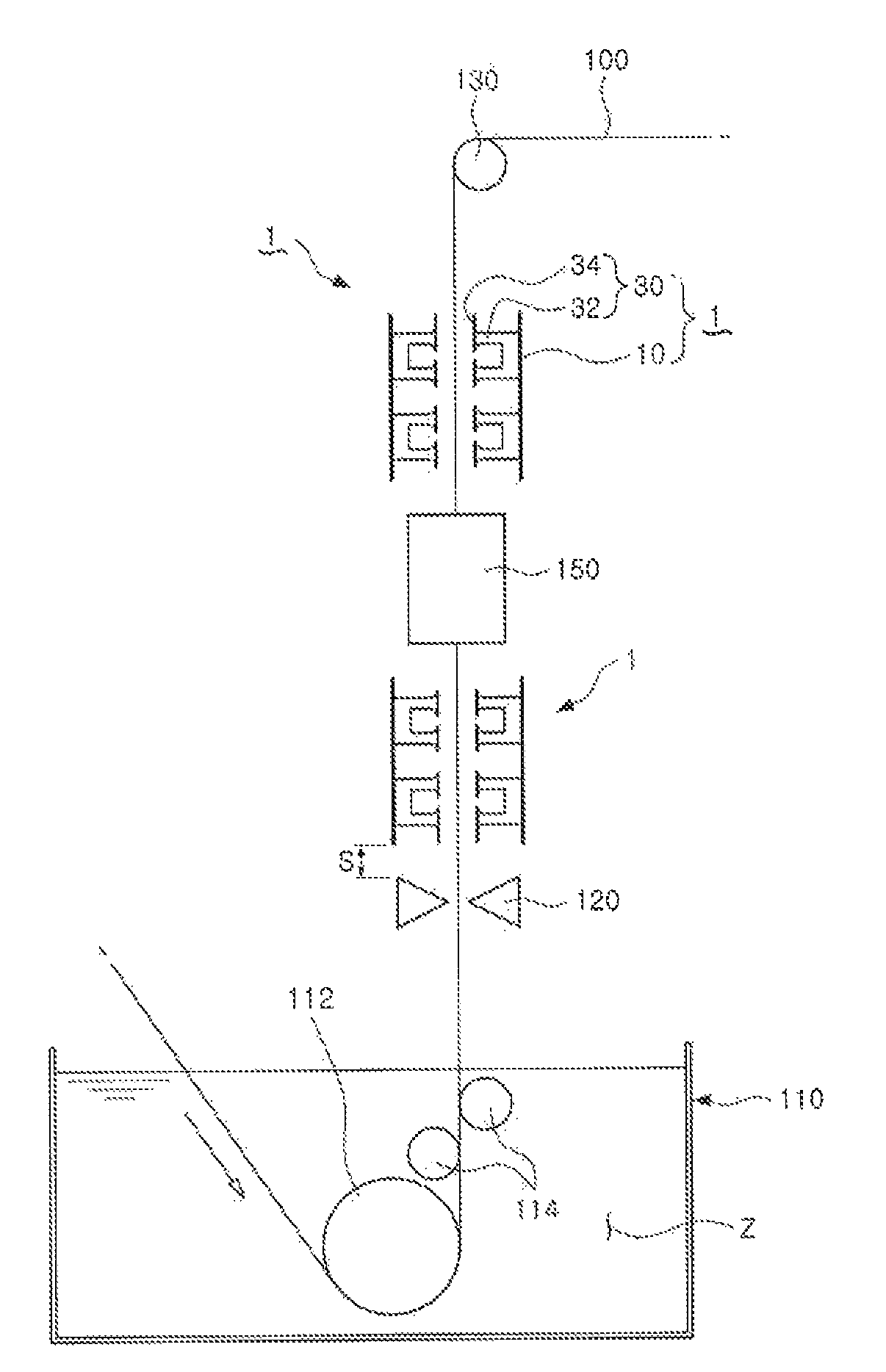
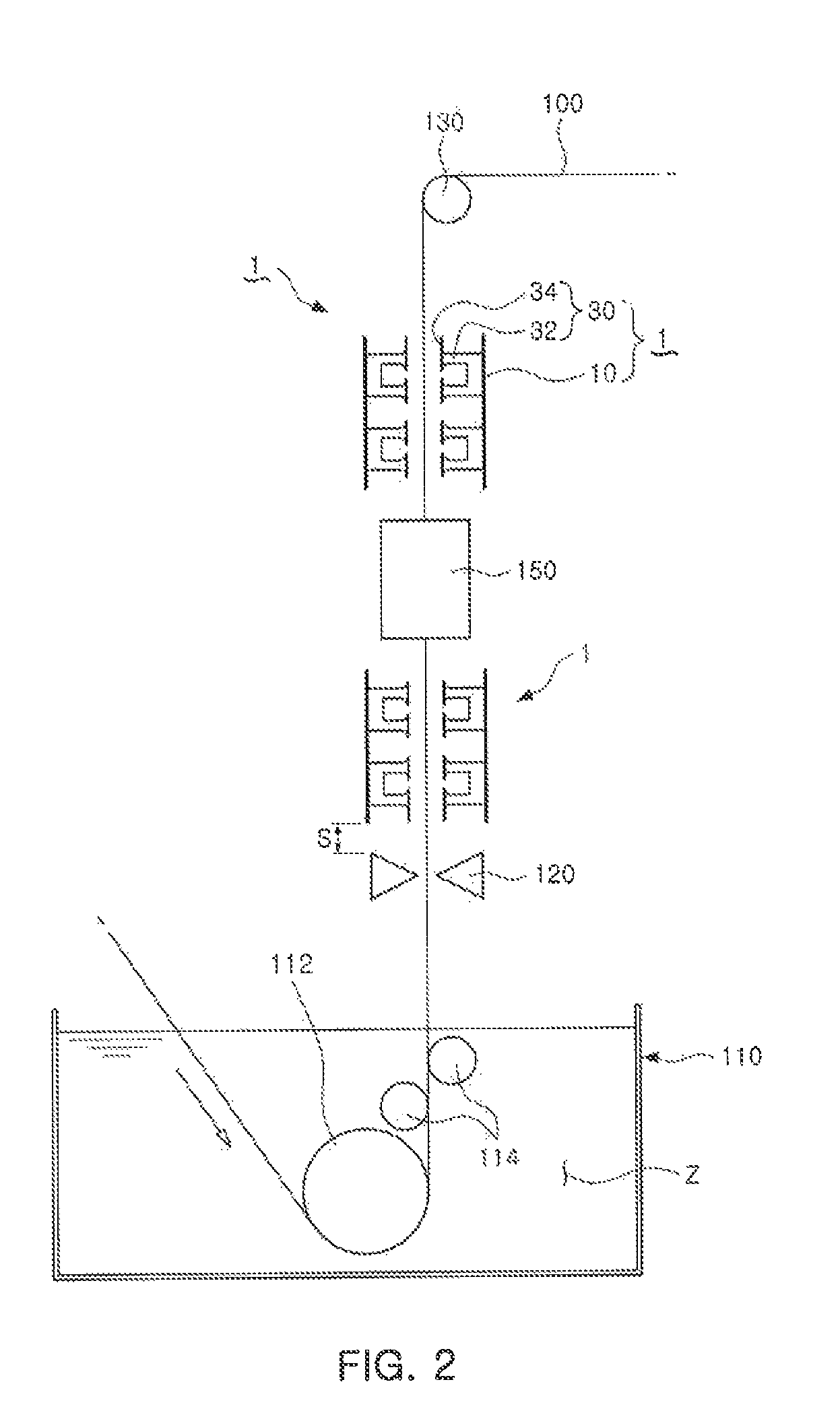
[0053]FIGS. 2 to 4 are schematic view of a steel strip stabilizing apparatus 1 according to the present invention.

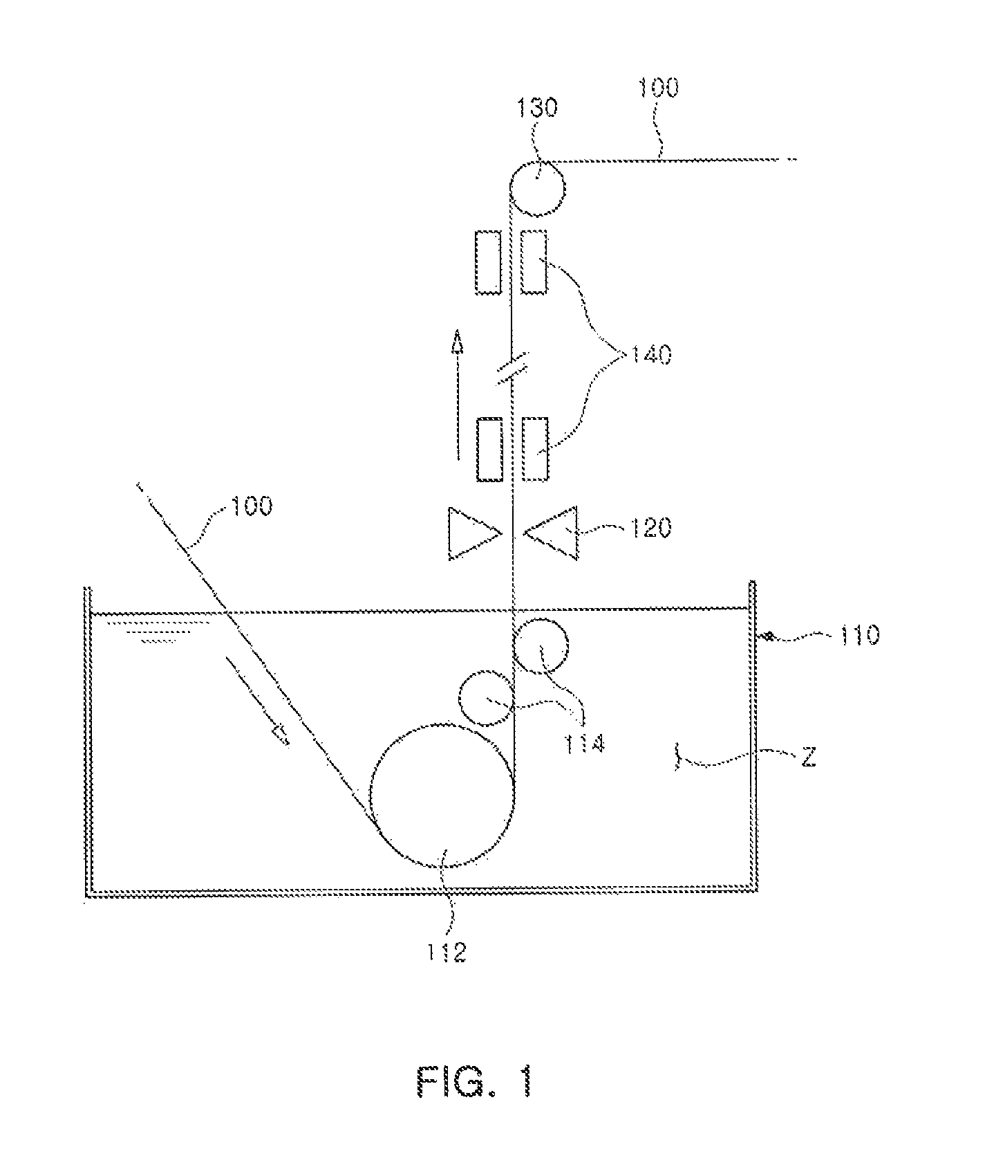
[0054]As shown in FIG. 2, the steel strip stabilizing apparatus 1 may perform shape correction and / or vibration suppression in a plated steel strip 100 that is plated with zinc by passing through a plating bath 110 of the zinc plating equipment of FIG. 1 in the current embodiment. Thus, the plating bath 110 including a sink roll 112 and a stabilizing roll 114, a gas wiping device 120, and an upper transfer roll 130 which are installed in a plating line will be denoted by the reference numerals of FIG. 1 according to the related art.

[0055]Here, the shape correction in the steel strip may represent a process in which a shape defect, which is bent in a width direction, of the steel strip passing through the gas wiping device 120, i.e., a C-curvatu...


PUM

PropertyMeasurementUnit
temperatureaaaaaaaaaa
distanceaaaaaaaaaa
distanceaaaaaaaaaa

Abstract

Provided is a steel strip stabilizing apparatus which allows shape correction and vibration suppression in a steel strip, particularly, plated steel strip, in a non-contact manner. The steel strip stabilizing apparatus includes an apparatus support body disposed on at least one side of a traveling steel strip and a steel strip stabilizing unit comprising a magnetic field generating pole disposed on the apparatus support body to face the steel strip and a pole expansion part configured to provide steel strip attraction force to a steel strip-side end of the magnetic field generating pole so as to allow shape correction or vibration suppression in the steel strip. The present invention increases the (electro)magnetic attraction force on the plated steel strip that passes through a plating bath, and thereby effectively ensures shape (curvature) correction or vibration suppression (damping) in the plated steel strip and prevents plating variations in the steel strip, and ultimately makes it possible to improve the quality of the plating of the steel strip.

Description

TECHNICAL FIELD[0001]The present invention relates to a steel strip stabilizing apparatus which corrects a shape of a steel strip, particularly, a transferred plated steel plate or damps vibrations of the plated steel strip in a non-contact manner.[0002]More particularly, the present invention relates to a steel strip stabilizing apparatus which increases (electro) magnetic attraction force with respect to a plated steel strip passing through a plating bath to effectively correct a shape (curvature) or suppress (damp) vibrations in the plated steel strip, thereby ultimately improving quality in plating of the steel strip.BACKGROUND ART[0003]In recent years, demand for (zinc) plated steel strips, which enhance corrosion resistance, etc., have desirable aesthetic qualities, and in particular, are used as steel sheets for electronic products or automobiles, has rapidly increased.[0004]FIG. 1 illustrates a process for plating a steel strip, particularly, a zinc-plating process.[0005]For...

Claims


Application Information

Patent Timeline
Patent Type & Authority Patents(United States)
IPC IPC(8): C23C2/40B65H57/00C23C2/14B05C3/00C23C2/00
CPCC23C2/40B05C3/00B65H57/006C23C2/003C23C2/14C23C2/5245
Inventor JANG, TAE-INJEE, CHANG-WOONKWEON, YONG-HUN
Owner POHANG IRON & STEEL CO LTD
Why Eureka
Try Eureka