Diagnostic method for poppet valves and measuring device for carrying out said method

a technology of poppet valve and diagnostic method, which is applied in the direction of fluid tightness measurement, instruments, mechanical equipment, etc., can solve the problems of not disclosing indications and suggestions, and achieve the effect of improving the database of compared quantities

Active Publication Date: 2016-11-08
GEA TUCHENHAGEN GMBH
View PDF15 Cites 0 Cited by
  • Summary
  • Abstract
  • Description
  • Claims
  • Application Information

AI Technical Summary

Benefits of technology

[0051]The advantage of diagnosing with the force-displacement curve F1(h) or F2(h) in comparison to diagnosing with the force-time curve F1(t) or F2(t) is that significant events and state changes are assigned directly to the respective displacement position of the poppet valve and thus can much easier be interpreted than a time-based assignment. In addition, evaluating force-time curves while directly comparing current and earlier curves is difficult since unusual circumstances during the operation of the poppet valve which are not ascribable to state changes of the poppet valve but rather, for example, to outside influences, can lengthen or shorten the time axis of the displacement-time curve.
[0054]In regard to the comparison itself, the invention proposes three preferred variants. One first variant provides an accepted switching cycle measured at the start of the poppet valve's operation or life is respectively used for the comparison. This can for example be the switching cycle of a new poppet valve, or one after a specific clearly delimited break-in phase. The second variant proposes always comparing the measured, current switching cycle with the last measured and accepted one. In addition, the tolerance range according to the invention can be adequately shifted with the last measured and accepted switching cycle. In this manner, changes in the poppet valve (such as settling or temperature-related deformations) that do not originate from state changes of the poppet valve to be diagnosed can be compensated and do not generate an error or maintenance message, or an undesired control signal.
[0055]The third variant of the method enhances the database of compared quantities by comparing the measured, current switching cycle with the average of a predetermined number of most recently measured and accepted switching cycles. This average can be the so-called arithmetic average or the geometric average. It is also advantageous to use the so-called “floating” average in which the last measured switching cycle is incorporated in the respective averaging, and the oldest switching cycle is discarded. This type of averaging has the same effect as shifting the tolerance range associated with the above-described second variant of the method.
[0060]To execute the diagnostic method, the invention proposes a measuring device that is arranged on a poppet valve wherein the poppet valve has at least one closing element in a valve housing, wherein the valve housing is firmly connected to a drive via a lantern housing, wherein the drive is designed as a spring-piston drive supplied with pressurization medium, wherein at least one adjusting rod actuatable by the drive is provided for least one closing element and wherein an evaluation device assigned to the measuring device is arranged on the poppet valve. It has proven to be useful and in particular very practical to measure a reaction force generated by the actuating force in the lantern housing. According to the invention, it is proposed that the measuring device consists of at least one first measuring device formed by at least one expansion sensor, is arranged on the lantern housing, and is connected to an evaluation unit. The reaction force can be clearly discernible and is very easy to access for measuring in a geometrically very simple housing.

Problems solved by technology

The pressure and flow forces consisting of static pressure (overpressure, underpressure) and / or dynamic pressure (inflow) comprise the planned forces that result during the regular operation of a processing system in which the poppet valve is arranged; however, they also comprise unplanned forces such as pressure surges or shocks in the valve housing supplied with the respective fluid.
The aforementioned prior art also does not disclose any indications and suggestions of how to glean such information from the obtained measuring signals.

Method used


Image

  • Diagnostic method for poppet valves and measuring device for carrying out said method
  • Diagnostic method for poppet valves and measuring device for carrying out said method
  • Diagnostic method for poppet valves and measuring device for carrying out said method

Examples


Embodiment Construction

[0081]While this invention may be embodied in many different forms, there are described in detail herein a specific preferred embodiment of the invention. This description is an exemplification of the principles of the invention and is not intended to limit the invention to the particular embodiment illustrated.

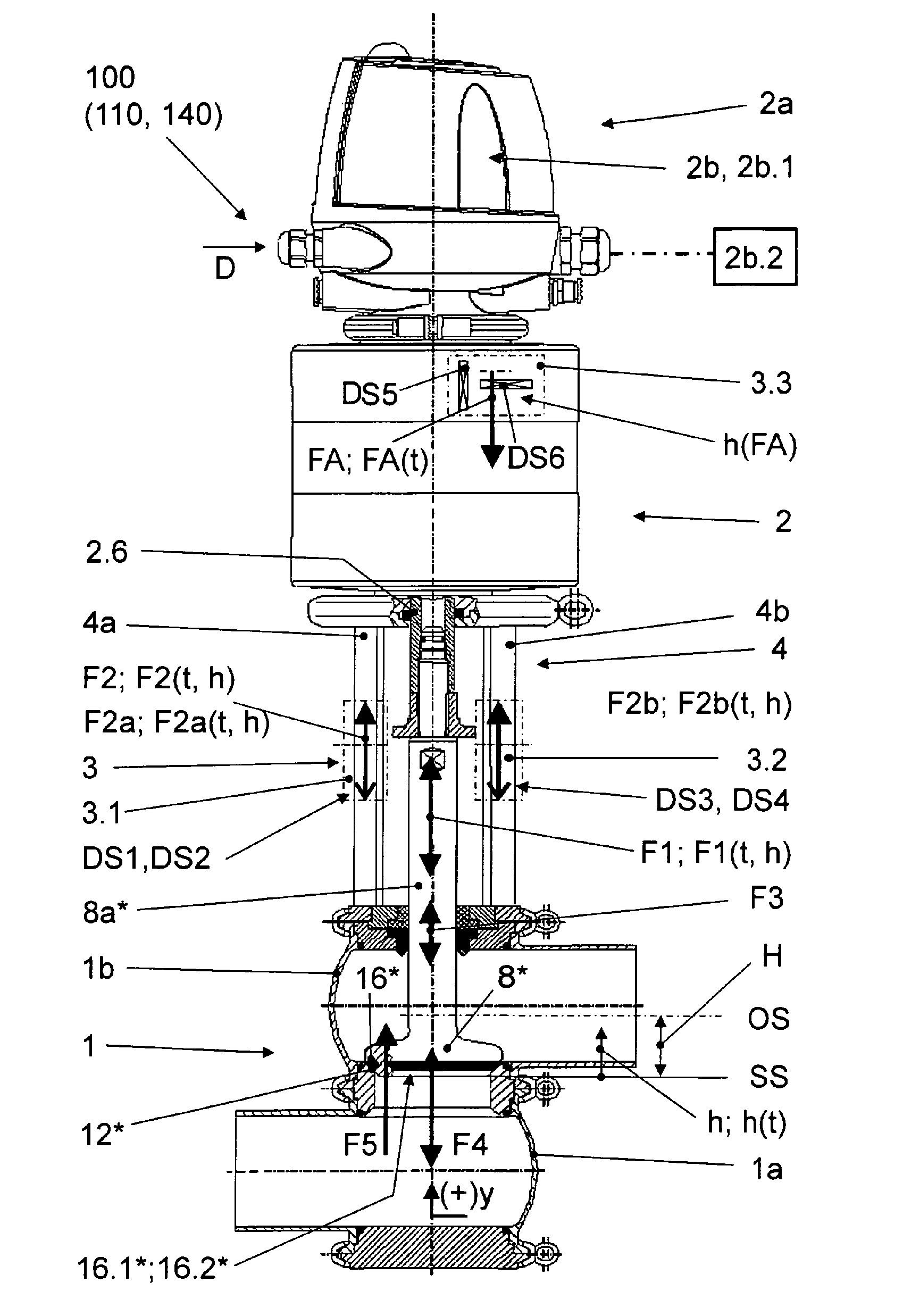
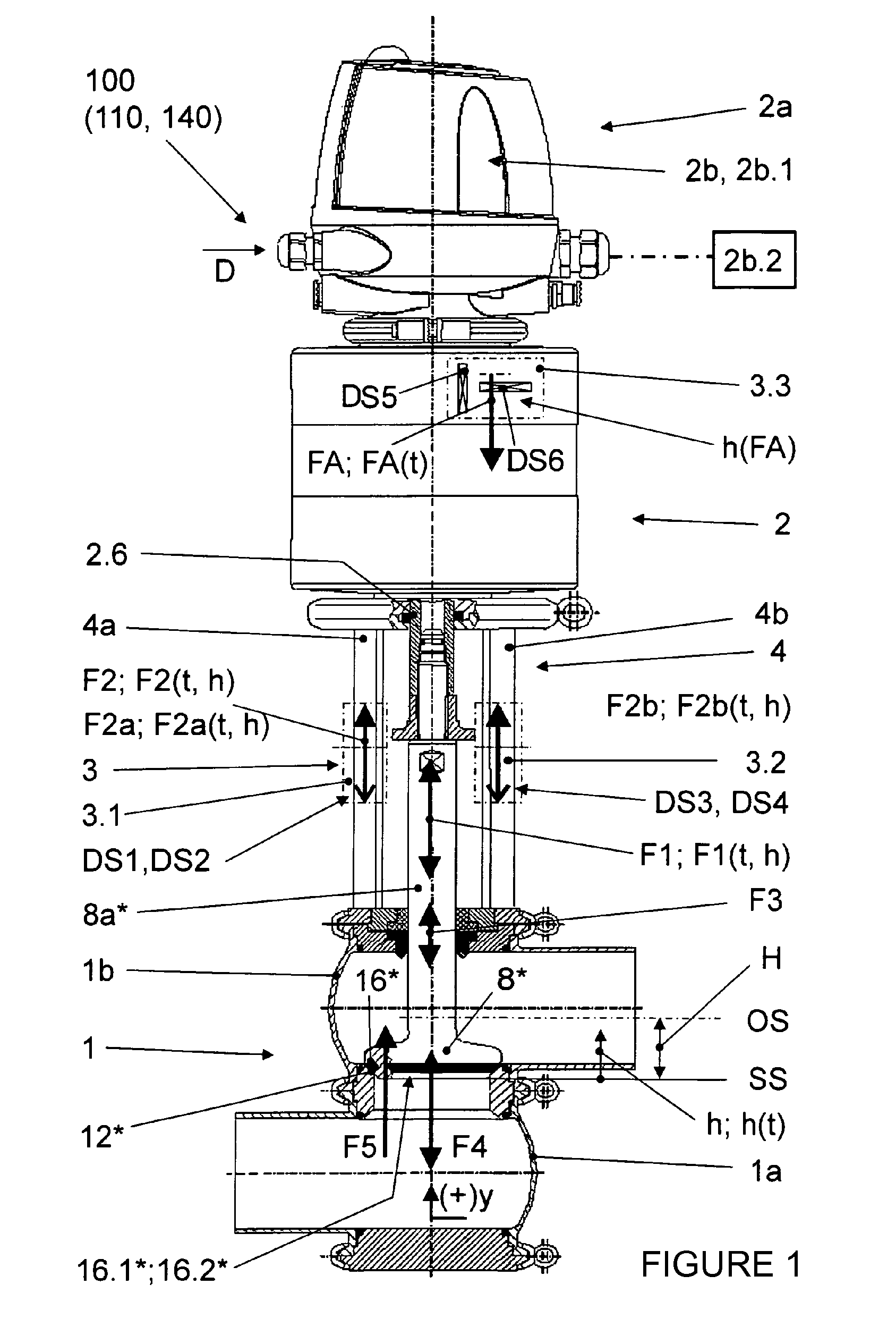
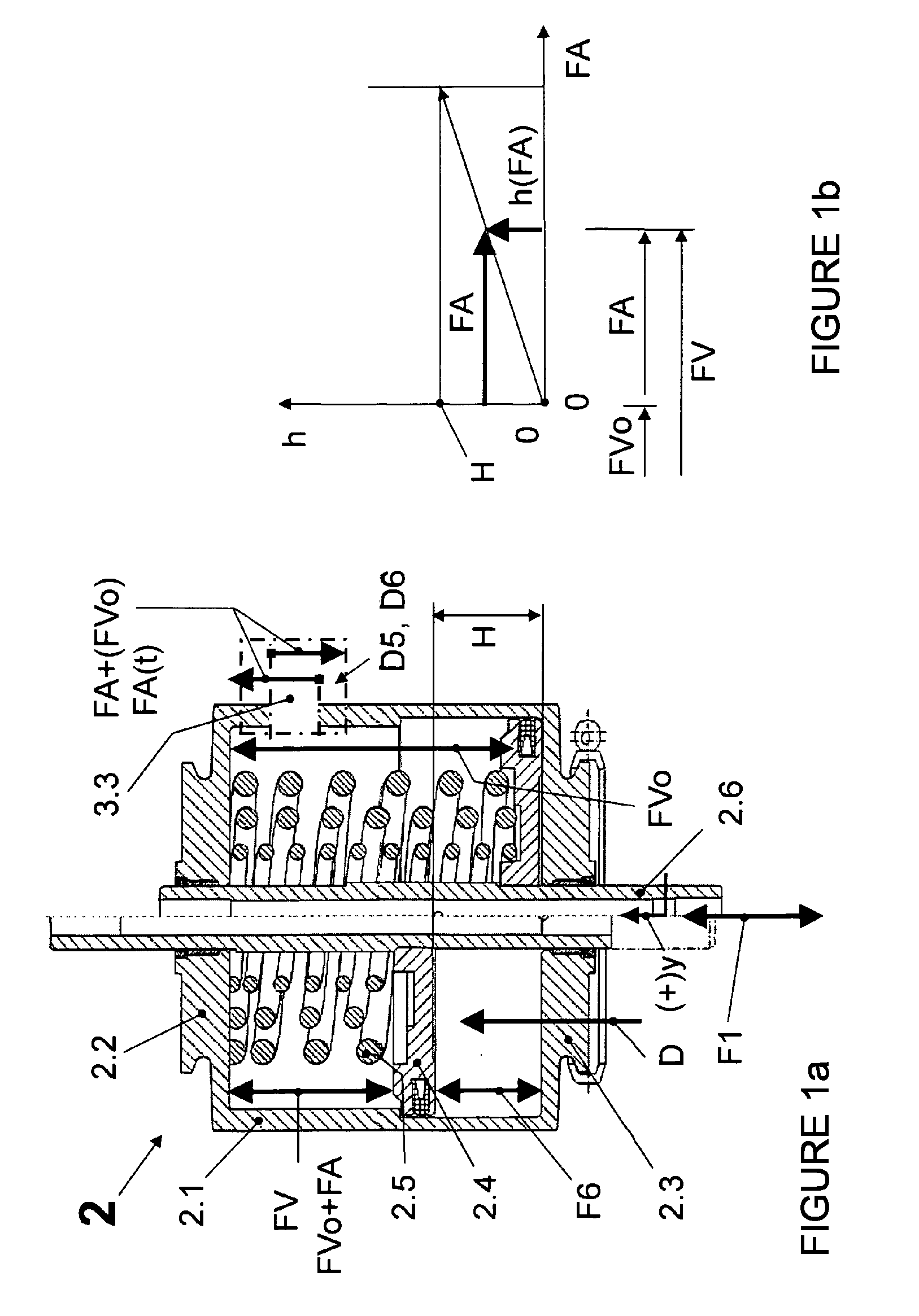
[0082]In the above, it has been sufficiently noted that information on the operating status of the poppet valve 100 and its general status (the status for example of the seat seal, status of the rod leadthrough, material of the seat seal, etc.) can be gleaned from the interaction of forces in the lantern housing 4 depicted in FIGS. 1 and 2. The description of FIGS. 1 and 2 will be rounded out in the following by an additional summary of the respective design of the depicted shutoff valve 110 (FIG. 1) and a double seal valve 140 (not shown) and the double seat valve 120, 130 (FIG. 2), each time in conjunction with measuring devices according to the invention.

Shutoff Valve (FIG...


PUM

PropertyMeasurementUnit
actuating forceaaaaaaaaaa
forceaaaaaaaaaa
reaction forceaaaaaaaaaa

Abstract

The invention relates to diagnostic methods according to the preamble of the equivalent claims 1 and 2, with which the state of a poppet valve in the course of the switching cycles and / or events thereof, such as the occurrence of pressure shocks or surges during continuous operation is / are monitored continuously, the measured signals are stored and the stored measured signals are interpreted in a targeted manner and early indication of cases of damage is carried out. According to a preferred variant of the diagnostic method, said aim is achieved in that at the same time as the force-time curve of the actuating force or the reaction force (F1(t); F2(t)), a displacement-time curve (h(t)) of the displacement (h) of the at least one closing element (8*) is measured, in that the force-time curve of the actuating force or of the reaction force (F1(t); F2(t)) and the displacement-time curve (h(t)) are combined with each other and used to determine a force-displacement curve of the actuating force or the reaction force (F1(h); F2(h)), in that the current force-displacement curve of the actuating force (F1(h)) or the reaction force (F2(h)) of a switching cycle, in each case determined over the operating period or lifetime of the poppet valve (100), is compared with an earlier, stored curve, in that deviations are determined from the comparison, in that, within a predefined tolerance range for said deviations, the latter are accepted, and in that, when said deviations exceed the predefined tolerance range, a message and / or a control signal is / are generated.

Description

CROSS-REFERENCE TO RELATED APPLICATIONS[0001]This application is a U.S. National Stage Application which claims priority to PCT / EP2011 / 004488 filed Sep. 6, 2011, which claims priority to DE 10 2010 044 891.5 filed Sep. 9, 2010.STATEMENT REGARDING FEDERALLY SPONSORED RESEARCH[0002]Not applicableBACKGROUND OF THE INVENTION[0003]The invention relates to a diagnostic method for poppet valves with which an actuating force representing an action force that is generated by a drive of the poppet valve is measured for at least one closing element of the poppet valve in the form of a force-time curve, the actuating force is either measured directly or from the reaction force resulting from the actuating force in the poppet valve, wherein the actuating force or the reaction force is determined by measuring the expanding deformations caused therefrom, and the measured, current force-time curve of the actuating force or of the reaction force is saved and subjected to an evaluation. The poppet va...

Claims


Application Information

Patent Timeline
Patent Type & Authority Patents(United States)
IPC IPC(8): G01N33/00G01B5/30G01B7/16F16K1/44F16K37/00
CPCG01N33/00F16K1/446F16K37/0083G01B5/30G01B7/18
Inventor SUEDEL, MATTHIASFAHRENBACH, PETERPORATH, BERND
Owner GEA TUCHENHAGEN GMBH
Why Eureka
Try Eureka