Conveyor belt for plate elements and converting machine comprising such a belt

a technology of conveying belt and plate element, which is applied in the direction of belt fastening, printing, instruments, etc., can solve the problem that conveying belt cannot be used in a converting machine, and achieve the effects of reducing time, improving cost efficiency, and increasing production tim

Active Publication Date: 2016-11-29
BOBST LYON
View PDF25 Cites 23 Cited by
  • Summary
  • Abstract
  • Description
  • Claims
  • Application Information

AI Technical Summary

Benefits of technology

[0011]It is a primary aim of the present invention to provide a conveyor belt that can be easily fitted and dismantled. The present invention aims in particular to solve, completely or partially, the problems mentioned above. Yet another aim is to fit a conveyor belt in a machine for converting plate elements. A conveyor belt is designed to convey plate elements in a machine for converting the plate elements. The conveyor belt comprises a belt body. The belt body has longitudinal edges, joining edges, and a support surface shaped for supporting the elements. The conveyor belt comprises at least one assembly member arranged to join the joining edges. The assembly member extends in a direction of assembly which is oblique to the longitudinal direction.
[0015]Thus, such a conveyor belt, while maintaining correct register, improves the productivity of the converting machine because the time required to replace the conveyor belt is significantly reduced by virtue of the fact that it is joined up using an assembly member.
[0017]The perforations keep the plate elements firmly pressed against the belt body. The register is thus guaranteed both due to the oblique assembly, which reduces sideways movement of the driven belt body, and due to the vacuum keeping the plate elements in place with respect to the converting devices, which perform an action on said plate elements.
[0019]Thus, such a converting machine can offer increased production time and improved cost efficiency, because of the reduction in the time for which production is interrupted to replace the conveyor belt. The register is maintained by virtue of the depression or vacuum chamber.

Problems solved by technology

However, such a conveyor belt cannot be used in a converting machine in which a plate element must be held firmly and precisely in place against the belt.

Method used


Image

  • Conveyor belt for plate elements and converting machine comprising such a belt
  • Conveyor belt for plate elements and converting machine comprising such a belt
  • Conveyor belt for plate elements and converting machine comprising such a belt

Examples


Embodiment Construction

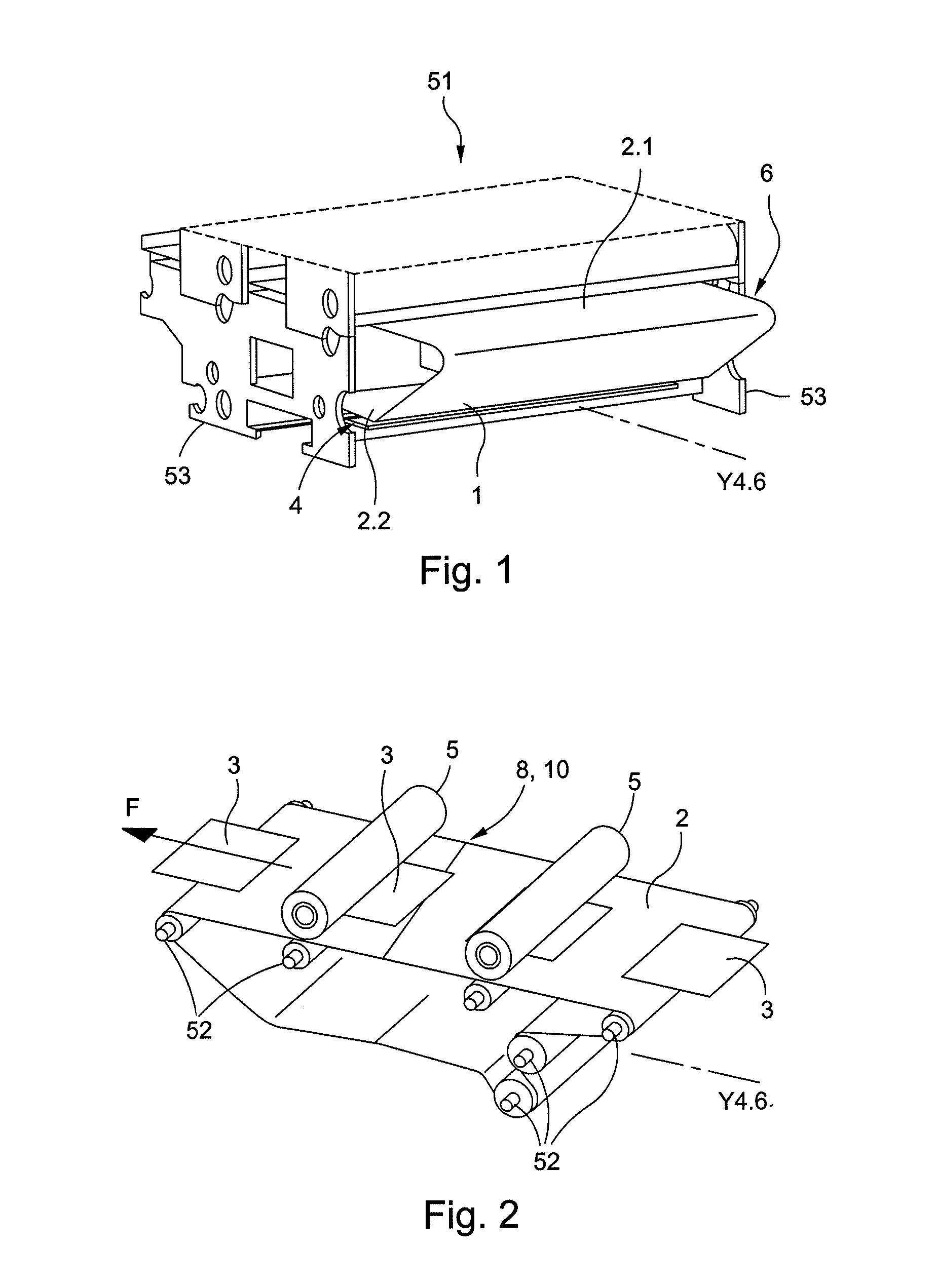
[0030]As shown in FIGS. 1 and 2, a converting machine 51 includes a conveyor belt 1. The converting machine 51 is in this case a four-color printing machine, in particular for printing color patterns on plate elements, i.e. plate cardboards 3. The cardboards 3 are conveyed by the belt 1 (arrow F in FIG. 2), in a longitudinal direction Y4.6. The printing machine 51 comprises successive printing cylinders 5, such as plate cylinders for flexographic printing.

[0031]The machine 51 includes a series of drive, return and tensioning rollers 52, for driving the belt 1 and keeping it tensioned. These rollers 52 are held rotatably by bearings and side frames 53. A vacuum chamber or chamber able for generating a depression is mounted beneath the belt 1 between the frames 53.

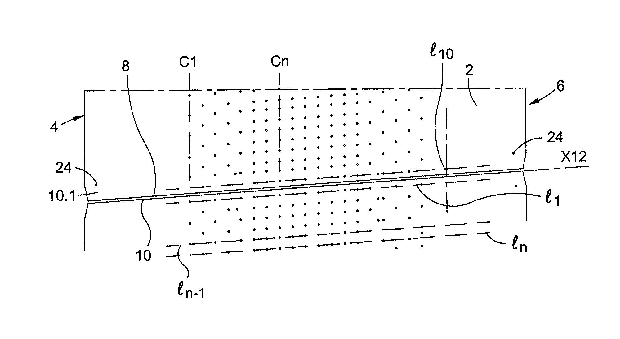
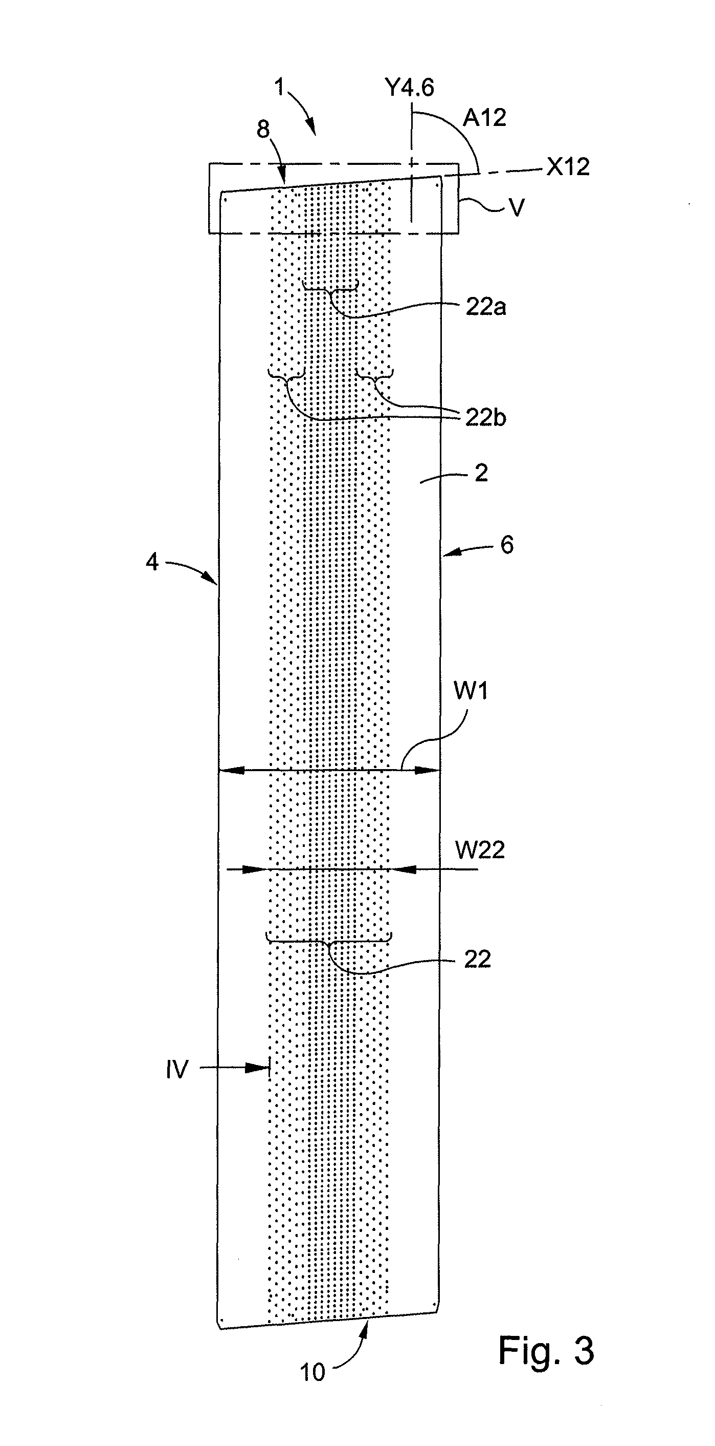
[0032]As shown in FIG. 3, the conveyor belt 1 comprises a belt body 2, which in this case is three-ply. The conveyor belt 1 has two longitudinal edges 4 and 6 and two “joining” edges 8 and 10. In the example of FIGS. 3 to 9,...


PUM


Abstract

A conveyor belt for conveying plate elements in a machine for converting the elements that includes a belt body with longitudinal edges, joining edges, and a support surface for supporting the elements, and at least one assembly member arranged to join the joining edges, and extending in a direction of assembly which is oblique to the longitudinal direction, the belt body having a plurality of perforations for obtaining a vacuum on the support surface to immobilize the elements.

Description

CROSS-REFERENCE TO RELATED APPLICATIONS[0001]The present application is a 35 U.S.C. §371 national phase conversion of PCT / EP2013 / 003866, filed Dec. 19, 2013, which claims priority of French Application No. 1262946, filed Dec. 28, 2012. The contents of both applications are incorporated by reference herein. The PCT International Application was published in the French language.FIELD OF THE INVENTION[0002]The present invention relates to a conveyor belt for conveying plate elements in a machine for converting the plate elements, and a converting machine such as a printing, folding and gluing machine comprising at least one such conveyor belt.FIELD OF APPLICATION[0003]The present invention applies to the field of converting cardboard in plate form, namely cardboard sheets, to produce packaging boxes or cases. Plate elements in cardboard sheet form are inserted one after the other into the converting machine, moving continuously in the direction of travel. They are automatically printed...

Claims


Application Information

Patent Timeline
Patent Type & Authority Patents(United States)
IPC IPC(8): B65G17/46F16G3/02B65G21/20F16G3/04B41J11/00F16G3/00
CPCB41J11/007B65G21/2036F16G3/02F16G3/04G03G15/6529
Inventor CUZIN, MARC
Owner BOBST LYON
Why Eureka
Try Eureka