Planar transmitter with a layered structure

Active Publication Date: 2016-11-29
PHOENIX CONTACT GMBH & CO KG
View PDF23 Cites 17 Cited by
  • Summary
  • Abstract
  • Description
  • Claims
  • Application Information

AI Technical Summary

Benefits of technology

[0021]According to an exemplary embodiment of the transmitter according to the invention, the first circuit is disposed on a first layer and the second circuit is disposed on a second layer, where an insulation layer is disposed between the first layer and the second layer, in each instance. In this connection, the insulation layer can be viewed as the main insulation layer, while further insulation layers can also be used as secondary insulation layers, within the first and/or second circuit, in order to make available electrically conductive coils having multiple windings, for example, in that the circuits have multiple layers, for example, which can be connected by way of an electrical contact, for example within the secondary insulation.
[0022]According to an exemplary embodiment of the transmitter according to the invention, it can be provided that the first circuit borders on the first magnetic layer, and the second circuit borders on the second magnetic layer.
[0023]In this manner, the other conventional insulations on the magnetic core, particularly between the individual circuits and the core, can be eliminated, because the core is divided into multiple parts, and the individual parts of the core can be assigned to the nearest circuits, in each instance, and to their potentials. This is possible, among other things because the parts of the magnetic core can assume different potentials, and are not electrically and mechanically connected with one another.
[0024]It is therefore provided that the first circuit borders on the first magnetic layer, and the second circuit borders on the second magnetic layer. In this connection, “border on” sho

Problems solved by technology

However, this is not an intrinsically safe tra

Method used


Image

  • Planar transmitter with a layered structure
  • Planar transmitter with a layered structure
  • Planar transmitter with a layered structure

Examples


Embodiment Construction

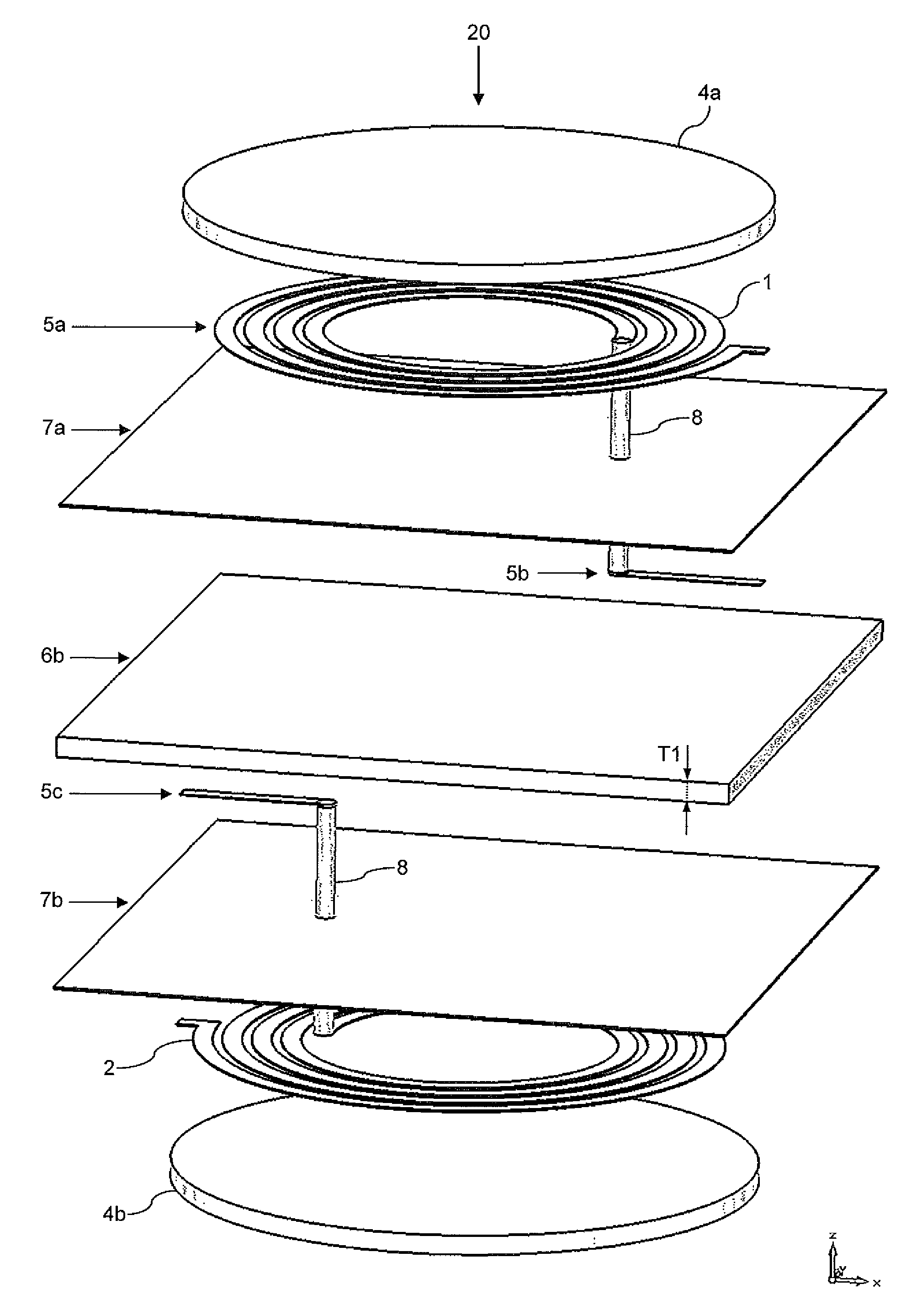
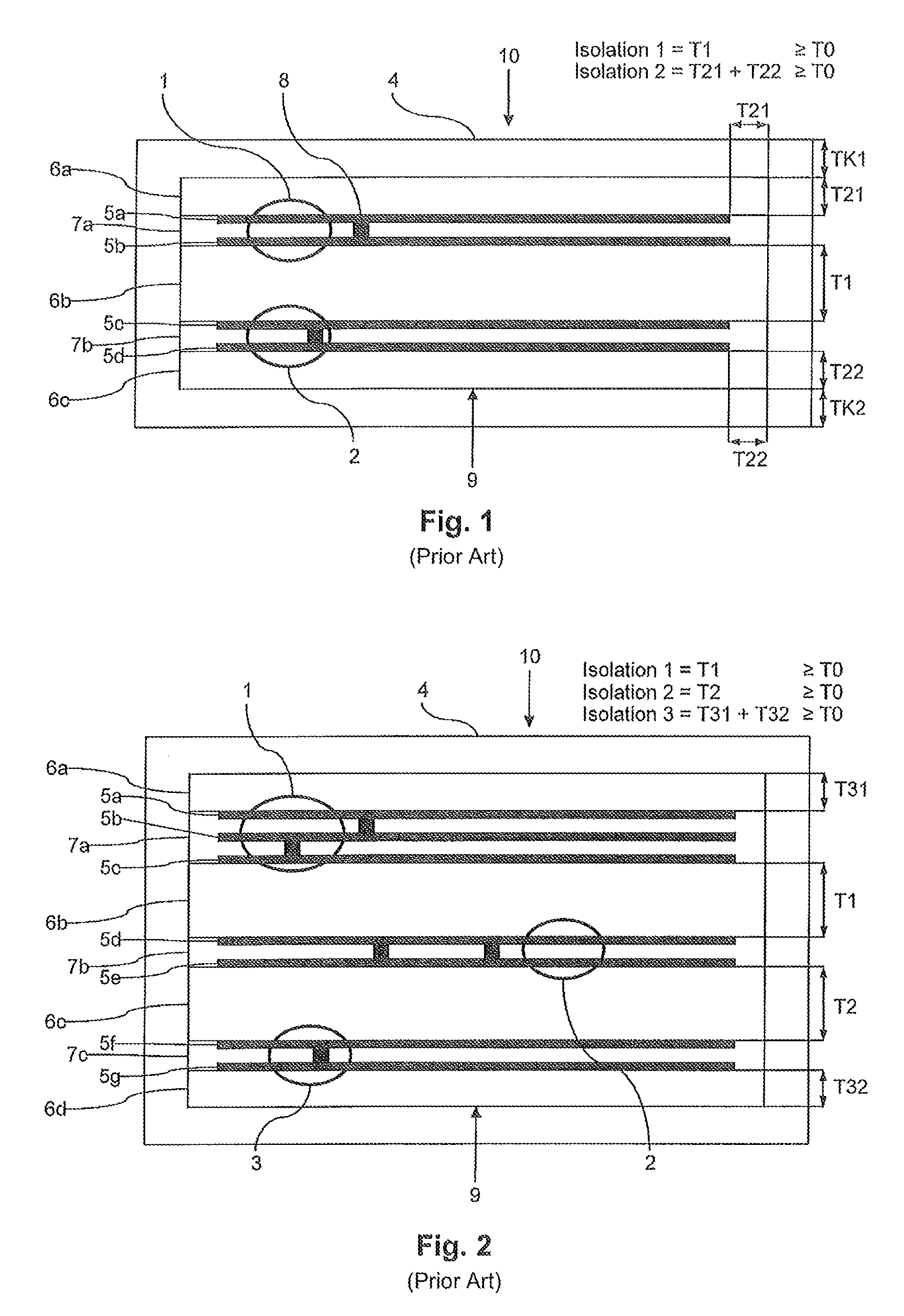
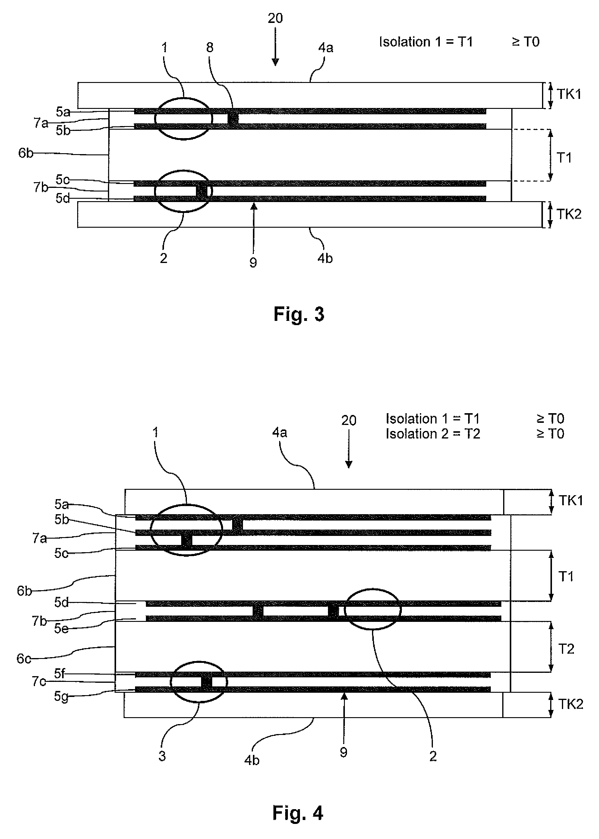
[0037]FIG. 1 shows a schematic representation of a conventional transmitter 10 having a first circuit 1 and a second circuit 2. The transmitter 10 is configured, for example, as an intrinsically safe circuit board transmitter, as known from EP 0 715 322 A1. The transmitter 10 has a ply structure with a primary side and a secondary side, which sides are formed, in each instance, by the two circuits 1, 2.

[0038]FIG. 1 shows a cross-section through a circuit board 9, which is enclosed by a core 4, where the core 4 penetrates the circuit board 9 at several locations. The penetration can be made available by means of milled areas in the circuit board 9, for example. The circuit board 9 has multiple plies, which is composed of layers of conductor tracks 5a to 5d and insulation layers 6a to 6c as well as 7a to 7b. In this special ply structure, the insulation layers can be divided into those (6a to 6c) that separate the individual circuits 1, 2 from one another and those (7a to 7b) that pro...


PUM


Abstract

A planar transmitter, particularly an intrinsically safe transmitter, having a layer structure having a first circuit and at least a second circuit, wherein the first circuit and the second circuit are galvanically separated from one another by means of at least one insulation layer. The transmitter has a first magnetic layer and a second magnetic layer, wherein the first magnetic layer delimits a first side of the layer structure, and the second magnetic layer delimits a second side of the layer structure, wherein the first magnetic layer 4a and the second magnetic layer are separated from one another and can be assigned to different potential groups.

Description

FIELD OF THE INVENTION[0001]The present invention relates, in general, to the field of interface technology with electronic components, which can be used for measurement, control, and regulation tasks, particularly as buffer amplifiers. These buffer amplifiers make galvanic separation between a primary circuit and a secondary circuit available, and are suitable for intrinsically safe operation, for example.[0002]The present invention relates to a transmitter, particularly a planar transmitter not susceptible to failure, which is suitable for intrinsically safe circuits and will be referred to as a planar, intrinsically safe transmitter hereinafter.BACKGROUND OF THE INVENTION[0003]Transmitters or transformers, and particularly intrinsically safe transmitters or transformers are used for galvanic separation of circuits according to different standards, where the transmitters can transmit not only energy but also signals and / or data.[0004]In different regulations and standards, for exa...

Claims


Application Information

Patent Timeline
IPC IPC(8): H01F27/28H01F17/04H01F27/24H01F27/32
CPCH01F27/2804H01F27/32H01F27/323H01F2027/2809H01F2027/2819
Inventor SCHOLZ, PETER-DOMINIK
Owner PHOENIX CONTACT GMBH & CO KG
Why Eureka
Try Eureka