Irrigated ablation catheter having irrigation ports with reduced hydraulic resistance

a technology of irrigated ablation catheter and hydraulic resistance, which is applied in the field of electrophysiologic catheter, can solve the problems of sudden death, life-threatening arrhythmia, cardiac arrhythmia, etc., and achieve the effects of improving the fluid flow of irrigation, increasing the fluid load on the patient, and increasing the velocity

Active Publication Date: 2016-12-06
BIOSENSE WEBSTER (ISRAEL) LTD
View PDF64 Cites 34 Cited by
  • Summary
  • Abstract
  • Description
  • Claims
  • Application Information

AI Technical Summary

Benefits of technology

[0018]The present invention is directed to a catheter adapted for mapping and ablating heart tissue with improved irrigation fluid flow into and out of the tip electrode. By considering and applying fluid characteristics and dynamics, the ablation tip electrode efficiently uses space and distributes fluid more uniformly and with higher velocity without necessarily using more power and energy at the irrigation fluid pump source or increasing fluid load on the patient.
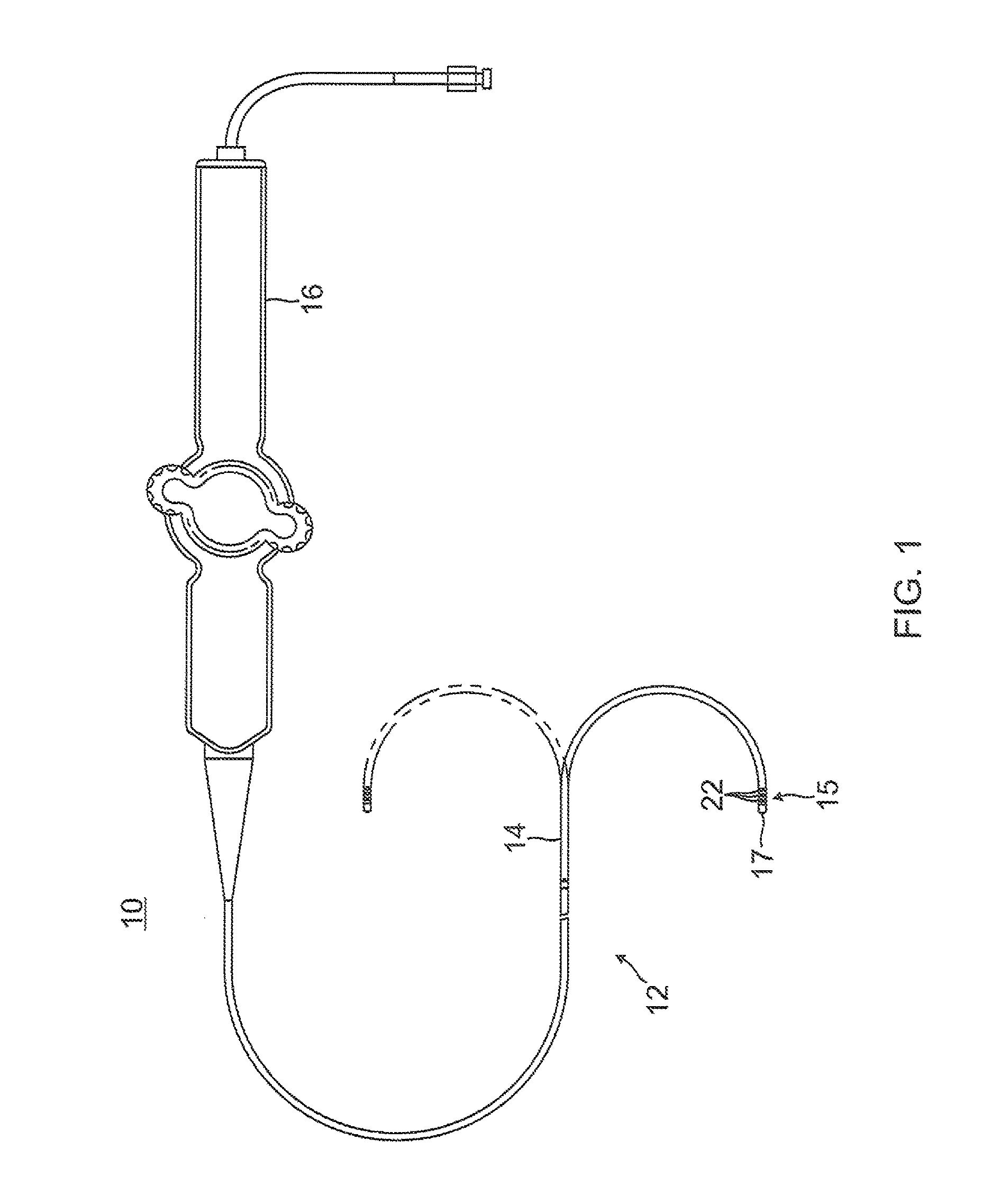
[0019]In one embodiment, an irrigated ablation catheter includes an elongated catheter body, a deflectable section distal to the catheter body and an ablation tip electrode. The tip electrode has a two piece design comprising a thin outer shell defining a cavity, and an internal member that fits inside the shell. The shell has a predetermined plurality of fluid ports, each with a predetermined diameter and each contributing to a total fluid output area of the tip electrode. The internal member has a plug member and a baffle member. The plug member includes a fluid inlet into the cavity of the tip electrode where the fluid inlet has a predetermined cross-sectional shape defining a fluid input area. Moreover, the cavity is designed to function as a plenum chamber by providing a variable inner cross-section so that momentum of the fluid entering the chamber is diffused and axial variability of fluid mass flow rate through the tip electrode fluid ports is reduced.
[0020]In a more detailed embodiment, the catheter of the present invention has a tip electrode wherein the diffusion ratio of total fluid output area to fluid input area that is less than 2.0, and a fluid port ratio of tip electrode shell thickness to fluid port diameter that is less than 3.25. Moreover, the tip electrode also has a fluid inlet aspect ratio greater than 1.0 where the fluid inlet has a noncircular (for example, oval or elliptical) radial cross-section defined by a wider dimension along one axis and a narrower dimension along another axis. The plenum chamber has an inner flow contour, for example, a bottleneck, where a narrow proximal portion opens to a wider distal portion so that fluid pressure increases while axial fluid velocity decreases which decreases axial momentum for a more uniform distribution of fluid in the tip electrode and thus more uniform flow of fluid exiting the fluid port.
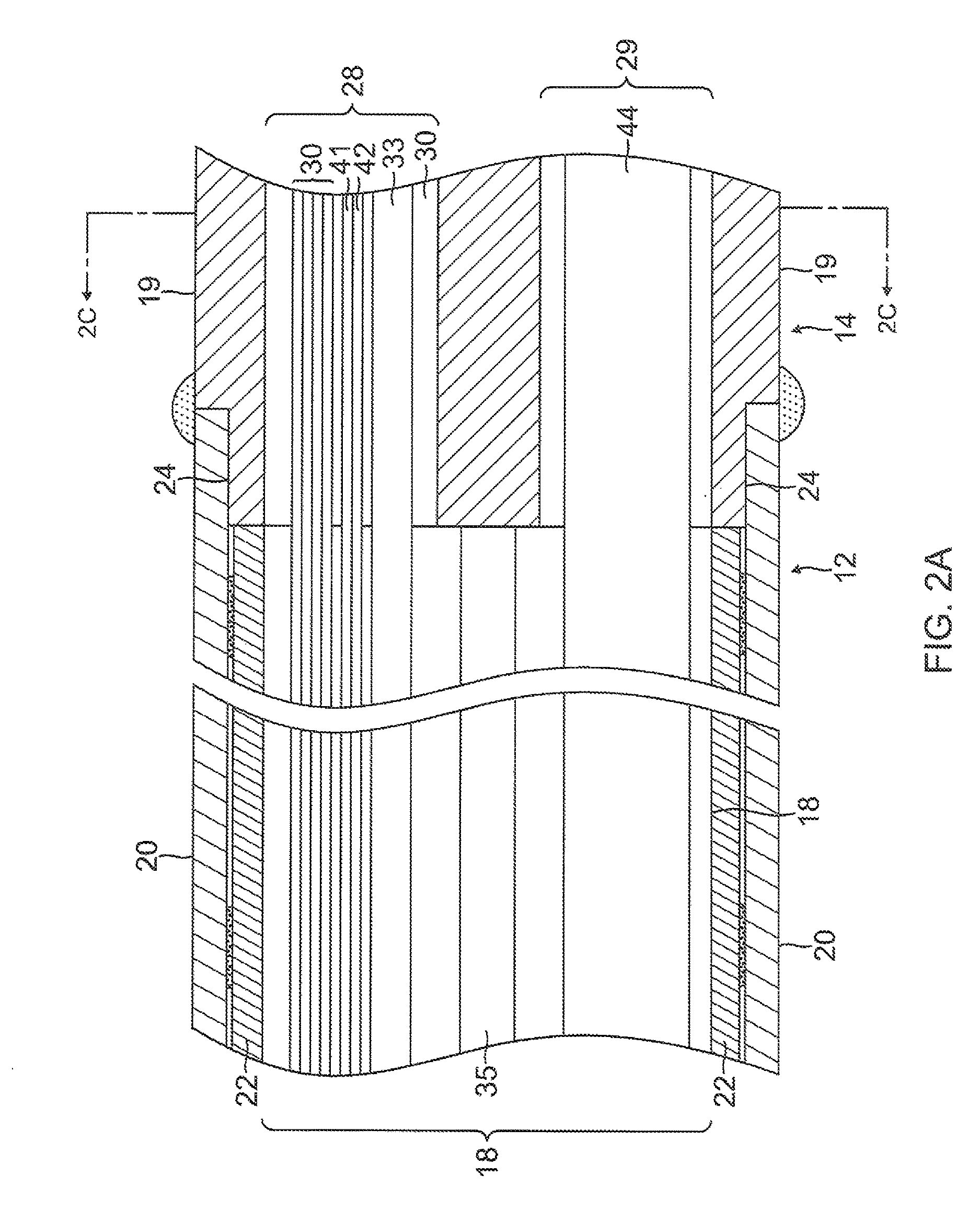
[0021]In a detailed embodiment, the internal member includes a distal baffle member and a proximal plug member connected by a stem. Distal ends of irrigation tubing, electrode lead wires, puller wires and thermocouple wires are anchored in the plug member. The plug has an inlet passage allowing the irrigation tubing to deliver fluid into the tip electrode. The inlet passage is off-axis and has a noncircular cross-sectional shape which efficiently uses the limited space in the tip electrode. The baffle member is shaped to diffuse fluid entering the tip electrode from the irrigation tubing as the fluid flows through the bottleneck of the plenum chamber. The baffle member is positioned on axis as it houses an electromagnetic position sensor advantageously in a centered distal position in the tip electrode. A cable for the sensor extends proximally from the sensor through a passage extending through the baffle member, the stem and the plug member.
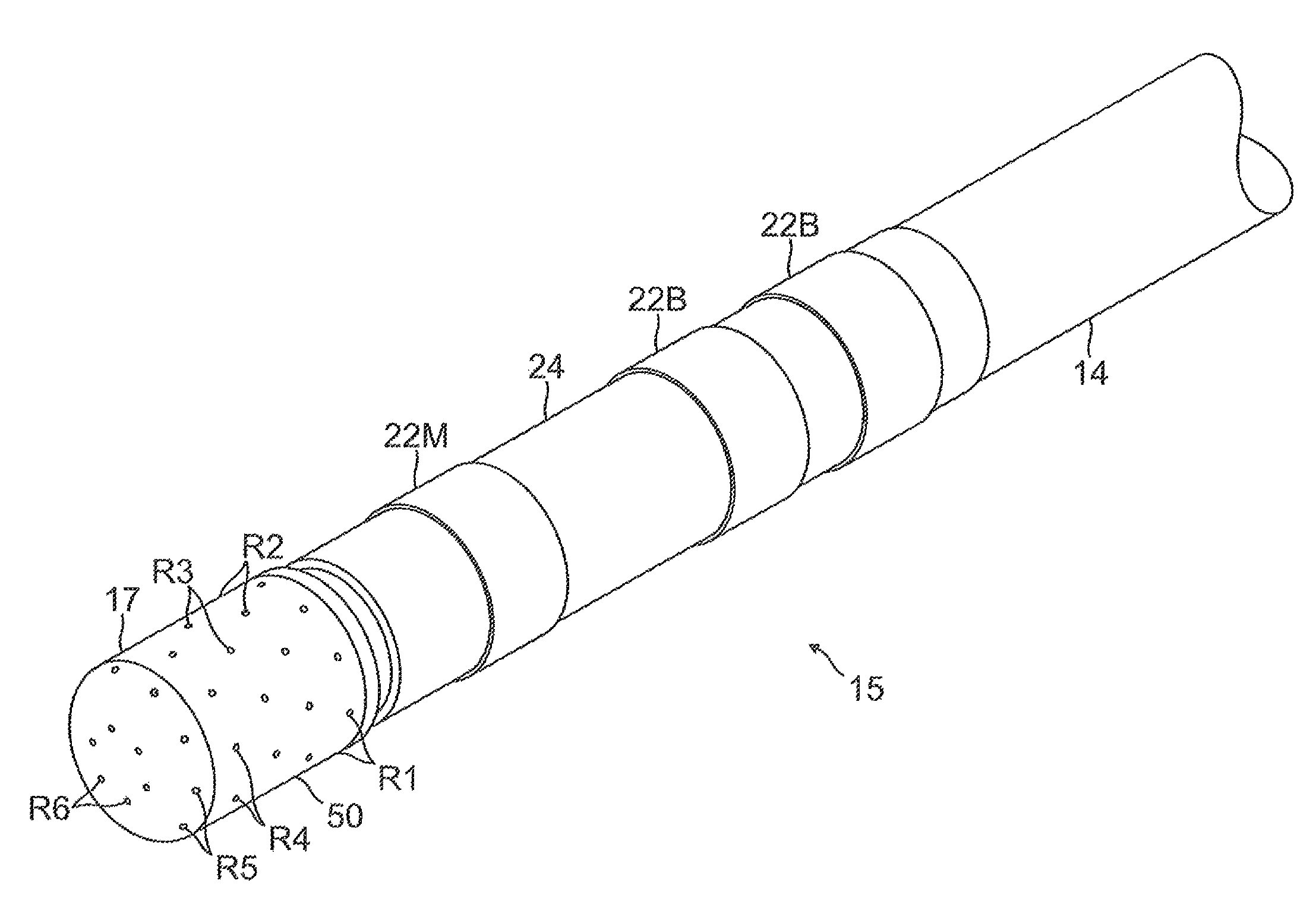
[0022]As another feature of the present invention, the fluid ports have a tapered cylindrical configuration with divergent walls that are formed by laser drilling. Laser drilling offers advantages, including no consumable / degradable tools, when compared to traditional screw machine or sinker EDM processes. The absence of degradable tooling allows laser drilling to be a more efficient process, because in-process adjustment is not required to compensate for tool wear. Additionally, the laser cutting mechanism is orders of magnitude faster than a comparable EDM process, with a single fluid port being drilled in seconds.
[0023]The divergent walls of laser drilled fluid ports are a result of transverse modes present in the focused laser beam and its interaction with surrounding substrate material (namely, the shell). The degree of taper is relatively small, ranging between 0 and 6 degrees, but the taper advantageously provides an increase in volumetric flow rate and a decrease in hydraulic resistance.

Problems solved by technology

Cardiac arrhythmias, and atrial fibrillation in particular, persist as common and dangerous medical ailments, especially in the aging population.
This is a potentially life-threatening arrhythmia because it may lead to ventricular fibrillation and sudden death.
The tissue is heated sufficiently to cause cellular destruction in the cardiac tissue resulting in formation of a lesion within the cardiac tissue which is electrically non-conductive.
However, there is typically a stagnant area between the electrode and tissue which is susceptible to the formation of dehydrated proteins and coagulum.
The arrangement of conventional internal catheter components such as irrigation lumens, location sensor and related electrical leads is limited by available cross-sectional area of the tip electrode.
The inclusion of the coupler results in an additional adhesive bond joint which contributes to a higher risk of fluid leaks.
Because of the temperature of the irrigating fluid and consequently the high viscosity of the fluid relative to the port diameter, and the length of the irrigation tubing, a significant amount of energy is required to pump the fluid to the tip electrode.
Such uneven distribution of fluid can cause undesirable “hot spots” which can compromise the size and quality of the lesions and require interruption of the ablation procedure so that coagulation can be removed from the tip electrode.
However, because the particles are sintered together, there can be concerns with particles detaching from the electrode and entering the bloodstream.
Although the sinker EDM process creates precise, minute geometries, it is typically an extremely slow process, with a single irrigation port taking upwards of five minutes to completely form.

Method used


Image

  • Irrigated ablation catheter having irrigation ports with reduced hydraulic resistance
  • Irrigated ablation catheter having irrigation ports with reduced hydraulic resistance
  • Irrigated ablation catheter having irrigation ports with reduced hydraulic resistance

Examples


Embodiment Construction

[0060]FIG. 1 illustrates an embodiment of a catheter 10 with improved irrigation flow through a tip ablation electrode 17. The tip electrode is configured to promote fluid flow into the tip electrode and dispersion of fluid therein in providing more uniform fluid coverage and flow at all locations on the exterior of the tip electrode. The catheter is therefore operable at lower flow rates with lower fluid load on the patient while providing improved cooling of the tip electrode. Moreover, a high fluid exit velocity at the tip electrode provides a “jetting” action that aids in creating a fluid boundary layer around the tip electrode which reduces the occurrence rate of char and / or thrombus during ablation. Fluid, e.g., saline or heparinized saline, can be transported to the ablation site from the tip electrode to cool tissue, reduce coagulation and / or facilitate the formation of deeper lesions. It is understood that other fluids can be delivered, as well, including any diagnostic and...


PUM


Abstract

An irrigated ablation catheter includes a tip electrode with a thin shell and a plug to provide a plenum chamber. The tip electrode has an inlet of a predetermined size and noncircular shape, and outlets in the form of fluid ports formed in the thin shell wall. The plurality of the fluid ports is predetermined, as is their diameter. Each fluid port has a tapered configuration, for example, a frustoconical configuration, with a smaller inlet diameter and a larger outlet diameter.

Description

RELATED APPLICATIONS[0001]This application is a continuation-in-part of and claims priority to and the benefit of U.S. application Ser. No. 12 / 769,592, filed Apr. 28, 2010, and U.S. application Ser. No. 12 / 770,582, filed Apr. 29, 2010, the entire contents of which are incorporated herein by reference.FIELD OF INVENTION[0002]The present invention relates to an electrophysiologic catheter that is particularly useful for ablation and sensing electrical activity of heart tissue.BACKGROUND OF INVENTION[0003]Cardiac arrhythmias, and atrial fibrillation in particular, persist as common and dangerous medical ailments, especially in the aging population. In patients with normal sinus rhythm, the heart, which is comprised of atrial, ventricular, and excitatory conduction tissue, is electrically excited to beat in a synchronous, patterned fashion. In patients with cardiac arrythmias, abnormal regions of cardiac tissue do not follow the synchronous beating cycle associated with normally conduct...

Claims


Application Information

Patent Timeline
Patent Type & Authority Patents(United States)
IPC IPC(8): A61B18/14A61B18/00
CPCA61B18/14A61B18/1492A61B2018/00029A61B2034/2051A61B2218/002A61B2018/00357A61B2018/00577A61M25/0127A61M2025/0073
Inventor CLARK, JEFFREY L.TOLA, JEFFRY
Owner BIOSENSE WEBSTER (ISRAEL) LTD
Why Eureka
Try Eureka