Ammonia storage management for SCR catalyst

a technology of ammonia storage and catalyst, which is applied in the direction of machines/engines, mechanical equipment, engine starters, etc., can solve the problems of insufficient ammonia storage, reduced nox conversion efficiency during certain operating conditions, and ammonia slippage from the catalyst, so as to reduce the emission of nitrogen oxides

Active Publication Date: 2016-12-06
FORD GLOBAL TECH LLC
View PDF9 Cites 6 Cited by
  • Summary
  • Abstract
  • Description
  • Claims
  • Application Information

AI Technical Summary

Benefits of technology

[0008]In this way, ammonia storage in an SCR catalyst may be preemptively boosted just after an engine-off, vehicle-off event so as to minimize an anticipated storage deficit at a subsequent vehicle-on event, engine-on event leading to an increased NOx conversion efficiency following the vehicle-on event. Further, ammonia injection for storage in an SCR catalyst may be adjusted to reduce delays in achieving target ammonia storage amounts in the catalyst for optimum NOx conversion efficiency following conditions which deplete ammonia storage in the catalyst, e.g., following cold-starts or thermal events such as DPF regeneration events.

Problems solved by technology

Ammonia that is used as a reductant in the catalyst may be desorbed from the SCR catalyst when the temperature increases resulting in ammonia slip from the catalyst.
Such closed loop approaches may lead to insufficient ammonia storage and reduced NOx conversion efficiencies during certain operating conditions, e.g., following cold starts or thermal events such as DPF filter regeneration events.
For example, vehicle-off (engine off) to vehicle-on (engine on) transitions may cause disturbances in the regulation of ammonia storage in an SCR catalyst for a desired NOx conversion efficiency.
Further, since active ammonia injection may not be possible at cold exhaust gas temperatures following a cold start event (e.g., less than 190° C.
), increasing ammonia storage in the SCR catalyst following a cold start event may be delayed so that ammonia storage in the catalyst remains under-stored following the vehicle-on event.
As another example, thermal events, wherein an SCR catalyst experiences active and rapid heating such as during a DPF regeneration event, may lead to substantial depletion of ammonia storage in an SCR catalyst.

Method used


Image

  • Ammonia storage management for SCR catalyst
  • Ammonia storage management for SCR catalyst
  • Ammonia storage management for SCR catalyst

Examples


Embodiment Construction

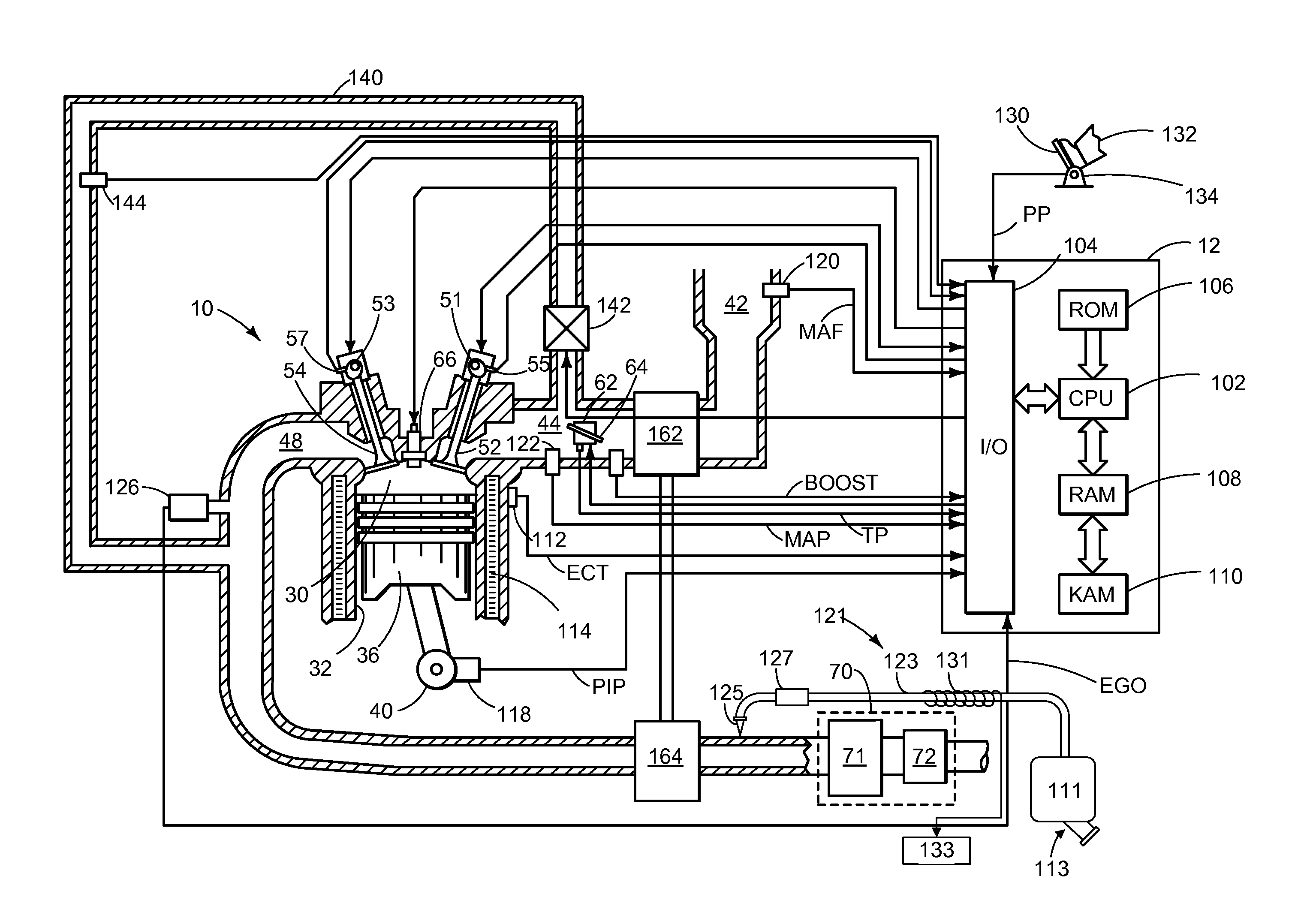
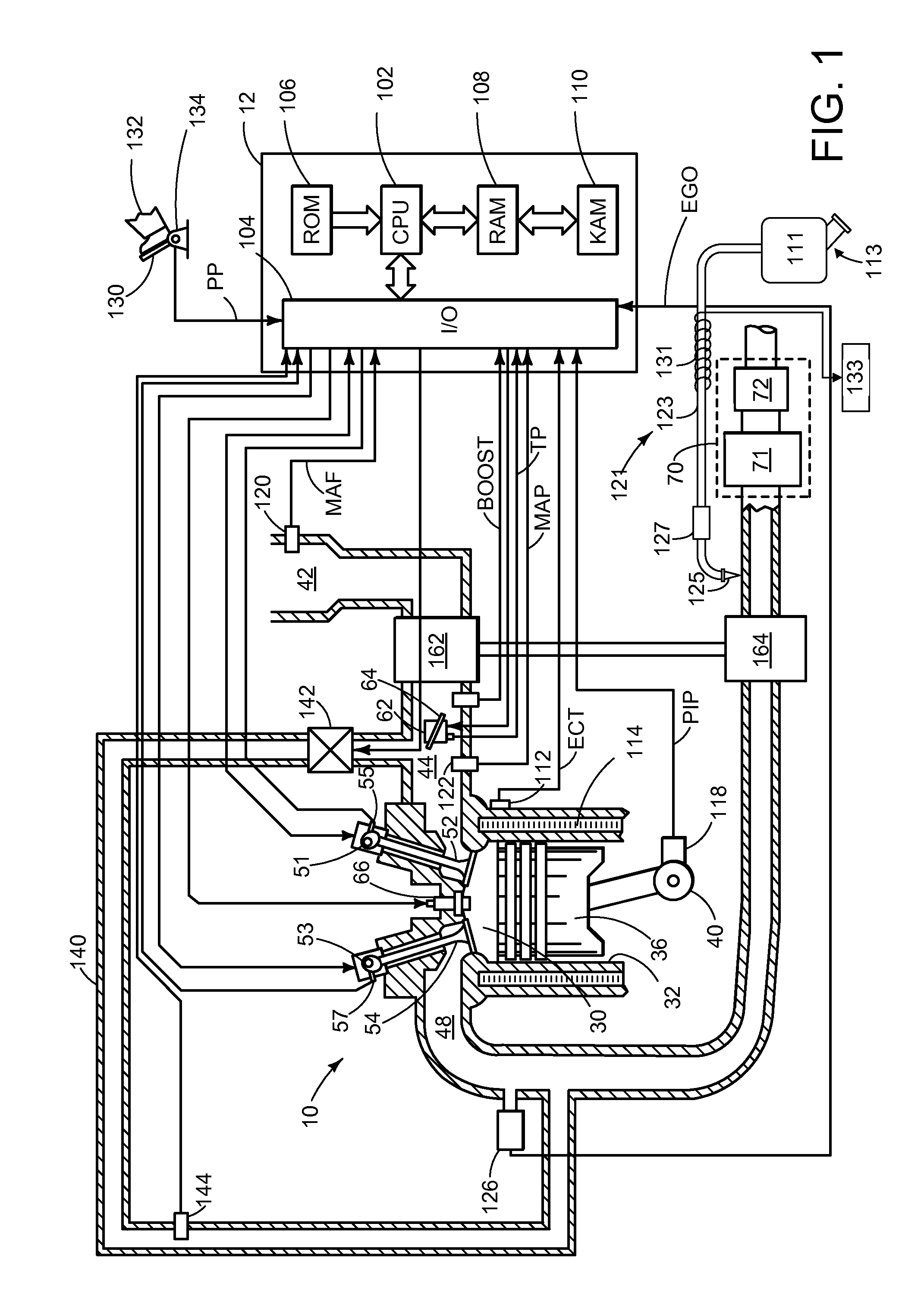
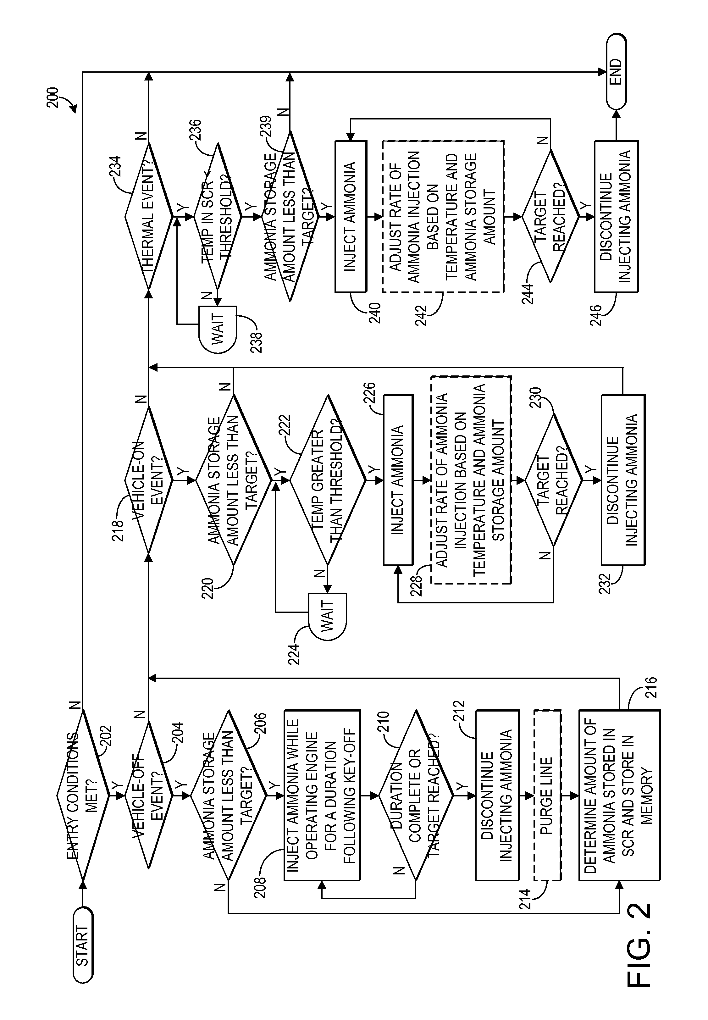
[0013]The following description relates to systems and methods for managing ammonia storage in a selective catalytic reduction (SCR) catalyst included in an emission control system of an engine, such as the engine shown in FIG. 1. As shown in FIGS. 2 and 3, an amount of ammonia stored in an SCR may be managed and replenished during various conditions in order to maintain a desired NOx conversion capability in the catalyst. For example, an additional amount of ammonia, e.g., in the form of urea or diesel exhaust fluid (DEF), may be injected following a vehicle-off event so that a sufficient amount of ammonia may remain in the SCR catalyst during a subsequent vehicle-on event after the engine cools down. Further, following a cold start event or following a thermal event, such as a diesel particulate filter (DPF) regeneration event, injection of ammonia may be adjusted to quickly replenish the SCR catalyst so that a desired NOx conversion capability of the catalyst is maintained.

[0014]...


PUM


Abstract

Various systems and methods are described for managing ammonia storage in an SCR catalyst. In one example approach, a method comprises, in response to a vehicle-off event, injecting ammonia during a final exhaust blowdown until a predetermined value of ammonia is stored in the SCR catalyst; and in response to a subsequent vehicle-on event when an amount of ammonia stored in the SCR catalyst is less than the predetermined value, injecting ammonia until the predetermined value of ammonia is stored in the SCR catalyst.

Description

BACKGROUND AND SUMMARY[0001]Diesel engines may include a selective catalytic reduction (SCR) catalyst in an emission control system to reduce emissions of nitrogen oxides (NOx) during engine operation. A reductant, such as ammonia in the form of urea or diesel exhaust fluid (DEF), may be injected, e.g., in the engine exhaust upstream of the SCR catalyst, so that ammonia is stored in the SCR catalyst to convert NOx into nitrogen and water.[0002]In some examples, an emission control system may include a diesel particulate filter (DPF) in addition to an SCR catalyst. When a DPF is used, thermal regeneration may be employed to clean the filter by increasing the temperature and burning soot that has collected in the filter. As the temperature of the DPF increases, the temperature of the SCR catalyst may also increase. Ammonia that is used as a reductant in the catalyst may be desorbed from the SCR catalyst when the temperature increases resulting in ammonia slip from the catalyst. The sl...

Claims


Application Information

Patent Timeline
Patent Type & Authority Patents(United States)
IPC IPC(8): F01N3/20
CPCF01N3/208F01N2900/1614F01N2900/1622Y02T10/24Y02T10/12Y02A50/20F01N3/20F02N9/00
Inventor UPADHYAY, DEVESHVAN NIEUWSTADT, MICHIEL J.LAMBERT, CHRISTINE KAYPHILION, DAVID WYNN
Owner FORD GLOBAL TECH LLC
Why Eureka
Try Eureka