
Twin turbo diesel aftertreatment system

a diesel exhaust and aftertreatment technology, applied in the direction of machines/engines, mechanical equipment, electric control, etc., can solve the problems of increasing the nox conversion efficiency typically lost, the exhaust temperature may be lower, and the difficulty in controlling, so as to improve fuel economy. the effect of improving the nox conversion efficiency, reducing the component size and precious metal loading of the aftertreatment devi

Active Publication Date: 2013-02-12
FORD GLOBAL TECH LLC
View PDF30 Cites 9 Cited by
  • Summary
  • Abstract
  • Description
  • Claims
  • Application Information

AI Technical Summary

Benefits of technology

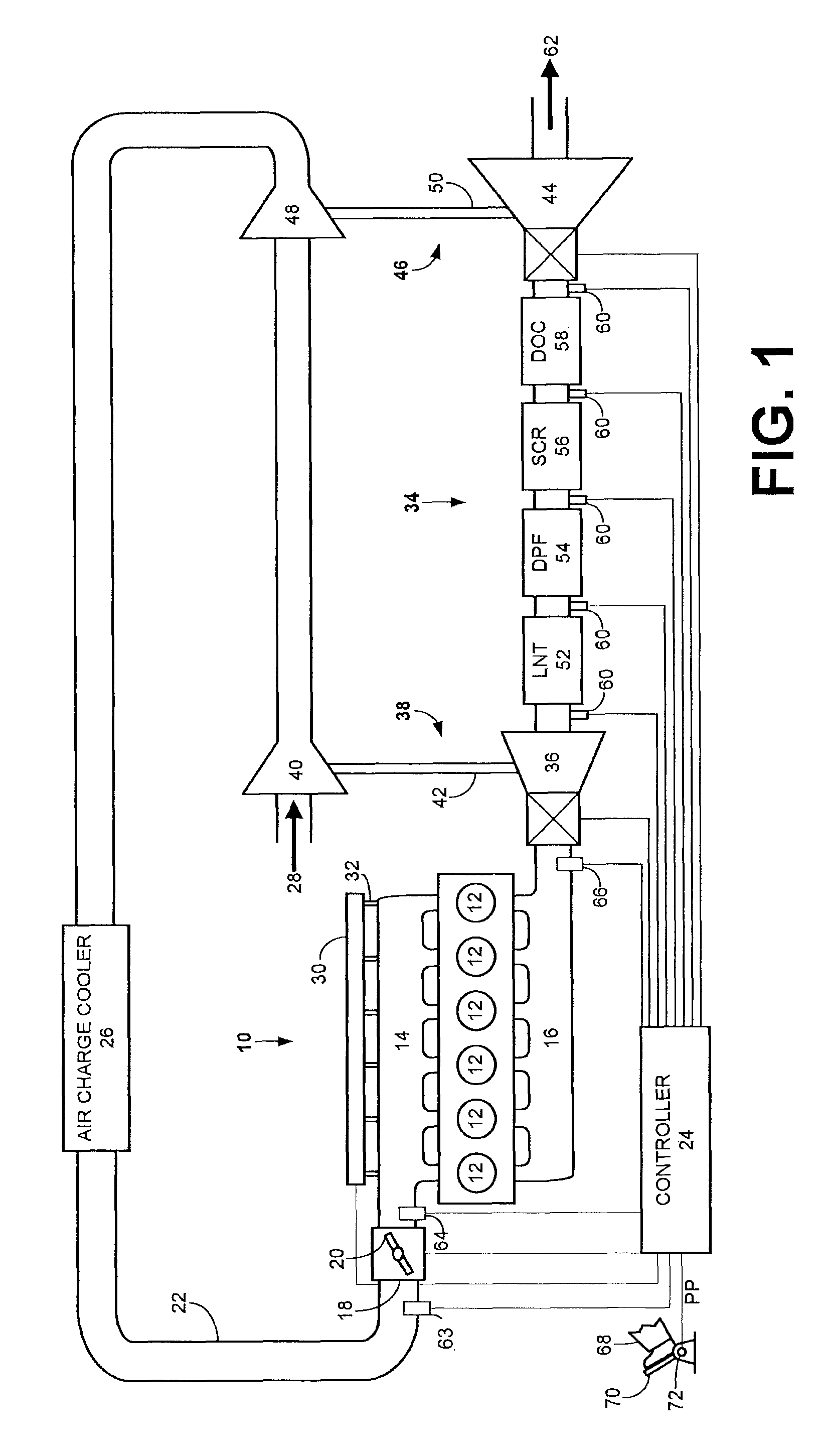
[0004]The inventors herein have recognized that by placing an emission control device in between two exhaust turbines, desired exhaust temperatures may be more easily achieved. Further, exhaust temperature may be more directly controlled, such as by the intake air throttle, fuel injection timing, and exhaust pressure. The exhaust pressure may be controlled when the turbines are variable geometry turbines (VGT), include wastegate valves, variable nozzles, etc. By adjusting the VGT, wastegate valves, etc. the amount of expansion of the exhaust gas via the turbines may be controlled.
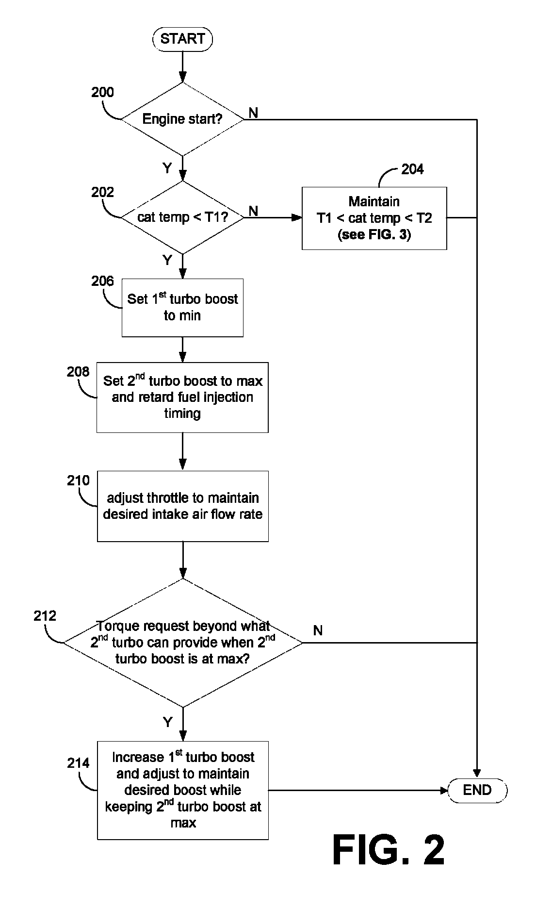
[0006]In such an approach the temperature of the exhaust, DPF, LNT, and / or SCR during non-warmed exhaust conditions, e.g. after engine cold starts from rest, may be substantially raised. Such a temperature increase in the emission control device may also increase NOx conversion efficiencies typically lost during a system warm up. Further, the exhaust temperature control of such an approach may eliminate the need to oxidize fuel in the DOC to control the temperature of the exhaust, DPF, LNT, and / or SCR, thus eliminating either fuel in oil dilution caused by late post fuel injection or the use of a separate fuel injector in the exhaust. As such, fuel economy may be improved. Additionally, the component size and precious metal loadings of the aftertreatment devices may be reduced due to higher temperatures in the aftertreatment devices at comparable engine speeds, loads, and warm up times.

Problems solved by technology

However, exhaust temperatures may be lower and difficult to control when such exhaust aftertreatment devices are positioned downstream of the turbocharger.
Such a temperature increase in the emission control device may also increase NOx conversion efficiencies typically lost during a system warm up.

Method used


Image

  • Twin turbo diesel aftertreatment system
  • Twin turbo diesel aftertreatment system
  • Twin turbo diesel aftertreatment system

Examples


Embodiment Construction

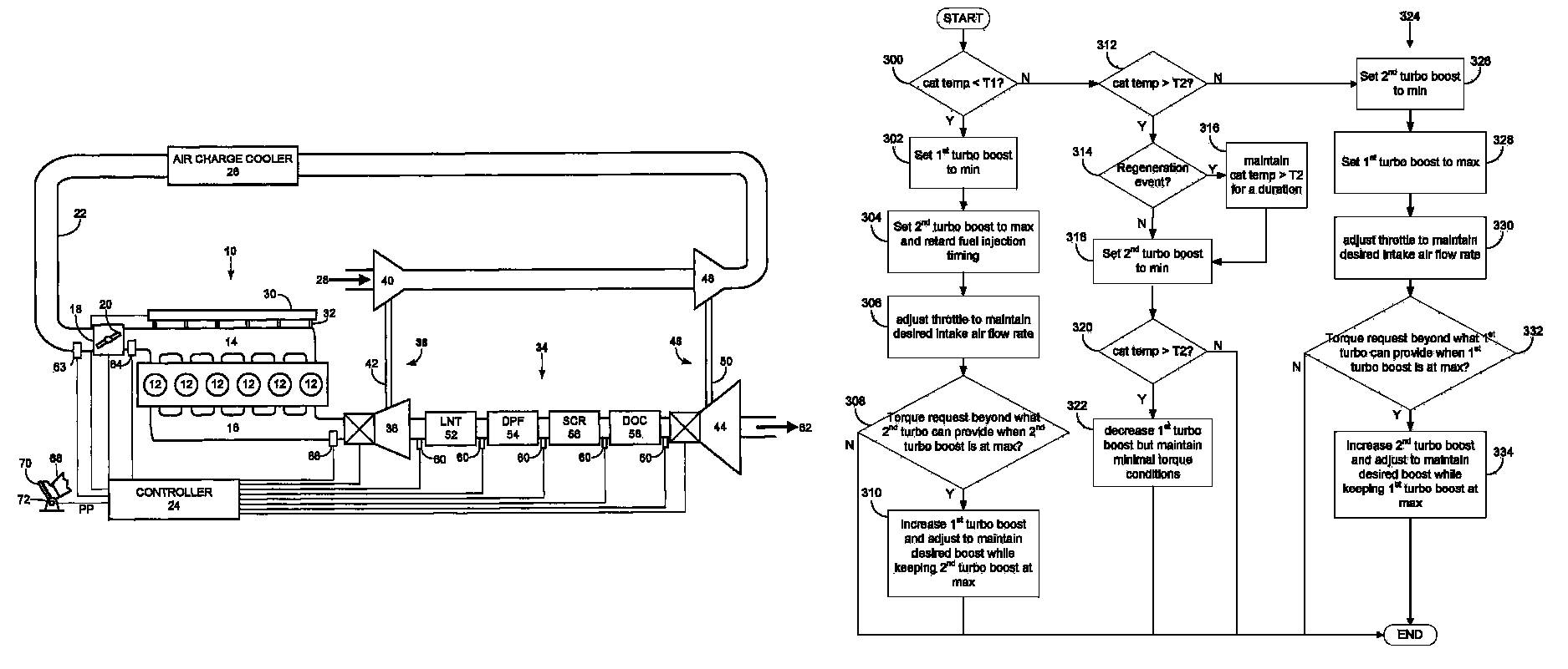
[0011]The following description relates to one or more emission control devices placed between two turbocharger exhaust turbines (e.g., one upstream and one downstream) and coupled to a combustion engine as shown in FIG. 1. In such a system, the exhaust temperatures may be coordinating control of various engine parameters, such as an intake air throttle, fuel injection timing, with various exhaust parameters, such as exhaust pressure. The exhaust pressure may be controlled by coordinating operation of the turbines in various operating modes, such as adjusting turbine operation via the variable geometry blade when the turbines are variable geometry turbochargers (VGT). Alternatively, in other examples, adjustment of turbine operation may include adjusting turbocharger wastegate valves, variable nozzles, etc. By adjusting the operation of the turbines among the various modes, the amount of expansion of the exhaust gas via the turbines may be controlled. Increasing the expansion across...


PUM


Abstract

Exhaust temperatures in emission control devices may be directly controlled by an intake air throttle, fuel injection timing, and exhaust pressure when an emission control device is placed between two variable geometry turbocharger exhaust turbines and coupled to a combustion engine. Such an approach may substantially raise the temperature of the exhaust aftertreatment devices in an emission control device during non-warmed exhaust conditions, leading to faster catalytic light-off.

Description

CROSS-REFERENCE TO RELATED APPLICATIONS[0001]This application claims priority from U.S. Provisional Patent Application No. 61 / 229,521, entitled “Twin Turbo Diesel Aftertreatment System,” filed Jul. 29, 2009, the disclosure of which is hereby incorporated by reference in its entirety and for all purposes.FIELD[0002]The present invention relates to a twin turbocharged diesel exhaust aftertreatment system.BACKGROUND AND SUMMARY[0003]Various methods are known for limiting diesel engine exhaust emissions of oxides of nitrogen (NOx), particulate matter, and hydrocarbons using diesel oxidation catalysts (DOC), particulate filters (DPF), oxides of nitrogen absorbers (LNT), and / or selective catalyst reduction (SCR) components positioned downstream of a turbocharger. However, exhaust temperatures may be lower and difficult to control when such exhaust aftertreatment devices are positioned downstream of the turbocharger. For example, such a positioning may require additional fuel to be oxidize...

Claims


Application Information

Patent Timeline
Patent Type & Authority Patents(United States)
IPC IPC(8): F01N3/00F02B33/44F02B37/013
CPCF01N13/009F01N3/103F01N3/2006F02B37/013F02B37/18F02B37/22F02D9/02F02D23/00F02D41/0007F02D41/0255F02B37/004F01N3/0842F01N3/021F01N3/2066F01N2430/08F02B29/0406F02D2200/0802Y02T10/144Y02T10/26Y02A50/20Y02T10/12
Inventor CHYO, TIMOTHY SUNG JAE
Owner FORD GLOBAL TECH LLC
Learn More