Eureka AIR delivers breakthrough ideas for toughest innovation challenges, trusted by R&D personnel around the world.

Radio frequency identification (RFID) tag having multiple antennas

Inactive Publication Date: 2016-12-06
ELECTRONICS & TELECOMM RES INST
View PDF11 Cites 11 Cited by
  • Summary
  • Abstract
  • Description
  • Claims
  • Application Information

AI Technical Summary

Benefits of technology

The patent describes a Radio Frequency Identification (RFID) tag that has multiple antennas. This RFID tag can maintain a high level of recognition for signals transmitted from its antennas, even when the environment in which it is located is not ideal for wireless communication. This means that the RFID tag can continue to work well even when it is exposed to complicated radio wave environments.

Problems solved by technology

However, it is known that when facing a channel environment such as multipath fading, the UHF-band RFID system may increase recognition errors, that is, may reduce a recognition rate.
However, in order to improve the speed in uplink communications in the RFID system while preventing reduction in a recognition rate, multiple antennas should be in an almost similar environment of electromagnetic waves, but in practice it is impossible that antennas are in the same or similar environment of electromagnetic waves all the time.
For this reason, some data may be lost during transmission, resulting in recognition errors of an uplink signal.
For example, in the case where a specific antenna, among a plurality of antennas, is in a bad environment of electromagnetic waves, an RFID reader may not accurately recognize an uplink signal transmitted by an RFID tag, or may mistakenly recognize an uplink signal as some other signal.
Even when the speed of uplink communications is increased by using a new technology, it is undesirable that a recognition rate of an uplink signal is reduced.

Method used


Image

  • Radio frequency identification (RFID) tag having multiple antennas
  • Radio frequency identification (RFID) tag having multiple antennas
  • Radio frequency identification (RFID) tag having multiple antennas

Examples


Embodiment Construction

[0026]The following description is provided to assist the reader in gaining a comprehensive understanding of the methods, apparatuses, and / or systems described herein. Accordingly, various changes, modifications, and equivalents of the methods, apparatuses, and / or systems described herein will be suggested to those of ordinary skill in the art. Also, descriptions of well-known functions and constructions may be omitted for increased clarity and conciseness. Terms used throughout this specification are defined in consideration of functions according to exemplary embodiments, and can be varied according to a purpose of a user or manager, or precedent and so on. Accordingly, the terms used in the following embodiments conform to the definitions described specifically in the present disclosure, and unless particularly defined otherwise, the terms should be interpreted as having the same meaning as commonly understood by one of ordinary skill in the art to which this invention pertains.

[...


PUM


Abstract

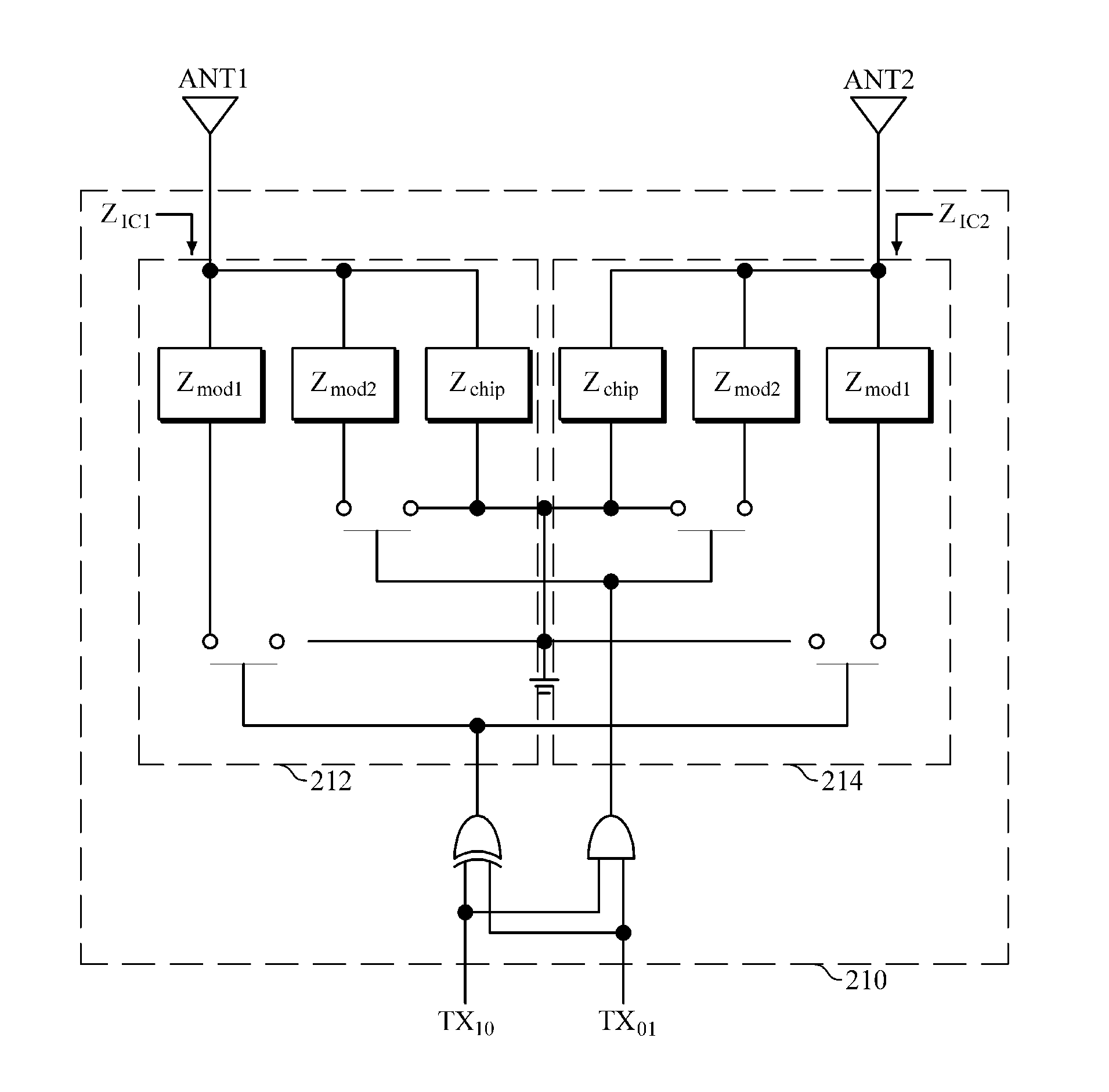
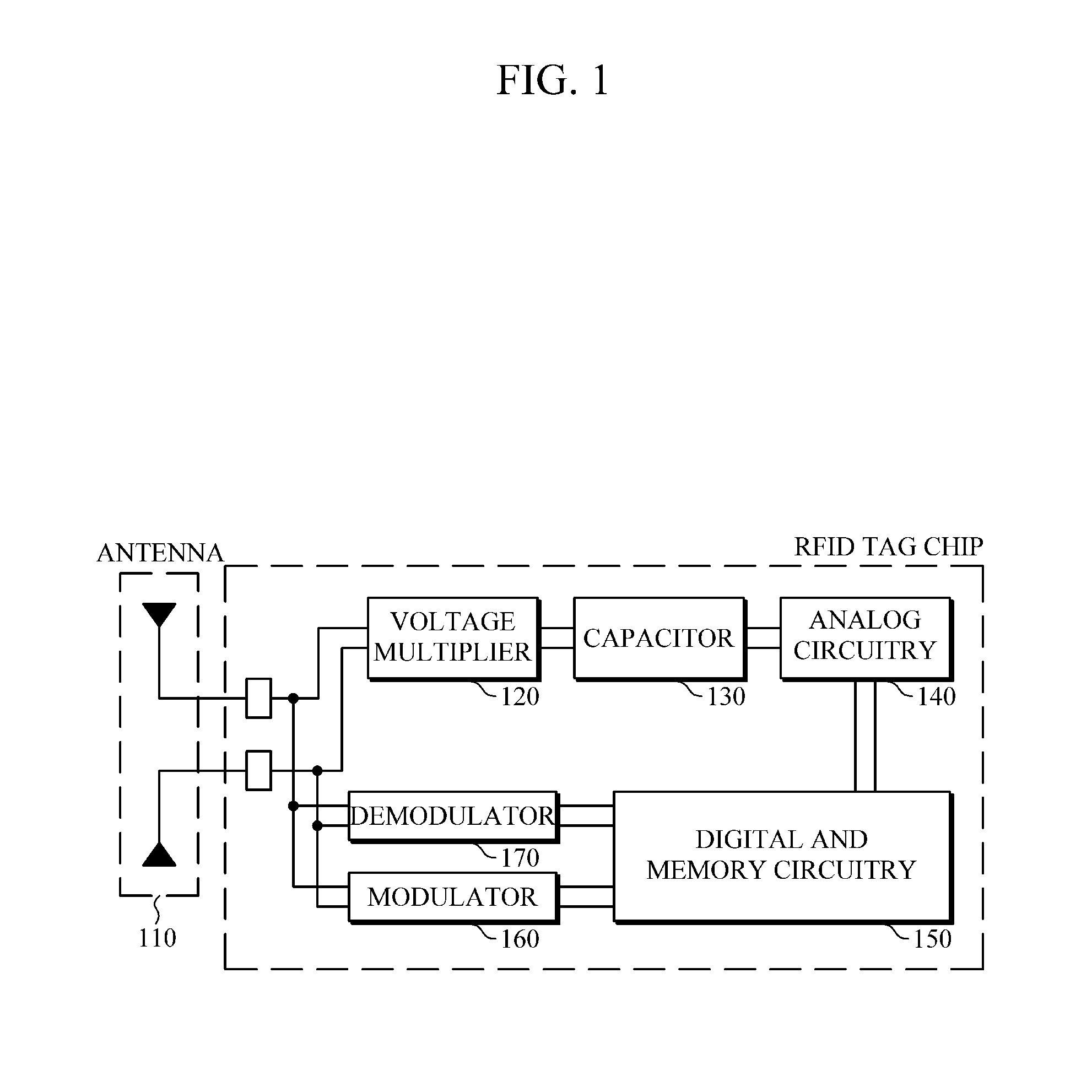
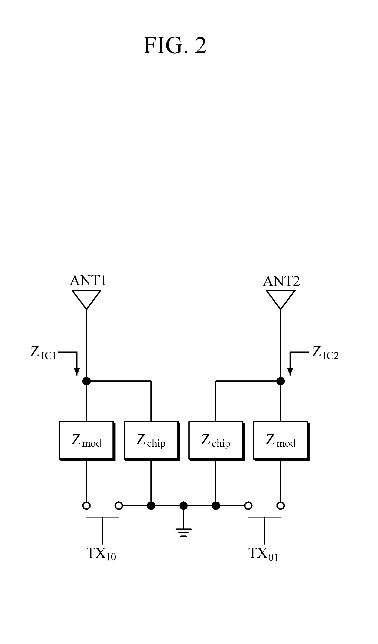
Provided is a Radio Frequency Identification (RFID) tag having a plurality of antennas. The RFID tag includes: a plurality of antennas each configured to backscatter received Radio Frequency (RF) signals; a digital and memory circuitry, which once the RF signals are received through the plurality of antennas, is configured to generate a series of programmed encoding signals based on identification information to be transmitted, and to output the generated signals; and a modulator configured to vary power of an uplink signal backscattered through the plurality of antennas based on the encoding signals input from the digital and memory circuitry, in which the modulator operates such that the power of the uplink signal backscattered through each of the plurality of antennas is equal regardless of types of the encoding signals.

Description

CROSS-REFERENCE TO RELATED APPLICATION(S)[0001]This application claims priority from Korean Patent Application No. 10-2015-0110683, filed on Aug. 5, 2015, in the Korean Intellectual Property Office, the entire disclosure of which is incorporated herein by reference for all purposes.BACKGROUND[0002]1. Field[0003]The following description generally relates to a technology for Radio Frequency IDentification (RFID), and more particularly to a technology for RFID tags which has multiple antennas to provide uplink communications through wireless communications of a backscatter modulation scheme.[0004]2. Description of the Related Art[0005]Radio Frequency IDentification (RFID) is a wireless technology to read or record information on tags by using radio frequencies, and is used to identify, track, or manage tagged items, animals, or people. Such RFID system has unique identification information, and is composed of a transponder or an RFID tag attached to objects or people, an interrogator ...

Claims


Application Information

Patent Timeline
IPC IPC(8): G06F19/00G06K19/077H01Q1/22G06K19/073H03C1/08
CPCG06K19/07794H01Q1/2225G06K19/073H03C1/08G06K19/0723G06K19/0724G06K19/0726H04L27/04
Inventor KIM, HYUN SEOKPARK, CHAN WON
Owner ELECTRONICS & TELECOMM RES INST
Why Eureka
Eureka Blog
Learn More