
Method and device for supporting group handover

a technology of mobile communications system and group handover, applied in the field of mobile communications system, can solve the problems of inability to support the movement between different cells, waste of network resources, and inability to meet the operator's demands on the train at a speed of 250-350, so as to reduce the failure of the handover process, ensure the continuity of service, and reduce the unnecessary signaling procedure

Active Publication Date: 2016-12-06
SAMSUNG ELECTRONICS CO LTD
View PDF7 Cites 3 Cited by
  • Summary
  • Abstract
  • Description
  • Claims
  • Application Information

AI Technical Summary

Benefits of technology

[0030]Aspects of the present disclosure are to address at least the above-mentioned problems and / or disadvantages and to provide at least the advantages described below. Accordingly, an aspect of the present disclosure is to provide a method and apparatus for supporting User Equipment (UE) group handover, which can ensure that a UE continuously receives data in the environment of high-speed movement, reduce unnecessary signaling procedure, and reduce possibility of network congestion.
[0036]A method or device set forth in the present disclosure is applicable to an architecture where a Serving Gateway (S-GW) and Packet Data Network (PDN) GW of an RN are co-located at the RN or to an architecture where the S-GW and the PDN GW of the RN are single entities (e.g., the S-GW / PDN GW is not co-located with the RN at the same entity). In addition, in a method or device set forth in the present disclosure, the S-GW of an RN and the S-GW of a UE served by the RN may be different. The cell of an RN has a unique 28 bit cell identifier along the high-speed railway, and the RN supports Public Land Mobile Network (PLMN) along the railway. The cell identifier of the RN may not include an identifier of a DeNB. A method or device set forth in the present disclosure can reduce unnecessary signaling procedure, the possibility of network congestion, and the signaling procedure of handover, so as to reduce the failure of the handover process and ensure the continuity of service.

Problems solved by technology

The existing relay is used for a fixed location and does not support motion between different cells.
An example of problem now faced by operators is when a user is on a train moving at a high speed.
That is, the service quality provided by the existing relay cannot satisfy the operator's demands on the train at a speed of 250-350 kilometers because of detrimental factors such as high noise, high penetration damage, serious Doppler frequency deviation, and lower handover success rate.
The X2 handover process is more optimal than the S1 handover, whereas the RN and the UE both are moving (e.g., on the train) and advancing at a high speed, and if multiple UEs simultaneously perform a handover process, it will lead to an unnecessary waste of resources for the network and will easily lead to a failure of the handover process.
However, there is currently no specific solution about how group mobility is performed.
If an RN and UEs served by the RN simultaneously perform a handover process, a method of ensuring coordinated work is also a problem that cannot be ignored.
So there is a problem of selecting the MME serving the UE, transmitting context information of the UE, and establishing a user plane transmitting path at network side for UE.
Second, there is a problem of letting the UE know of the change of information at the network side, e.g. change of Global Unique Temporary Identifier (GUMMEI) of a new serving MME.

Method used


Image

  • Method and device for supporting group handover
  • Method and device for supporting group handover
  • Method and device for supporting group handover

Examples


embodiment one

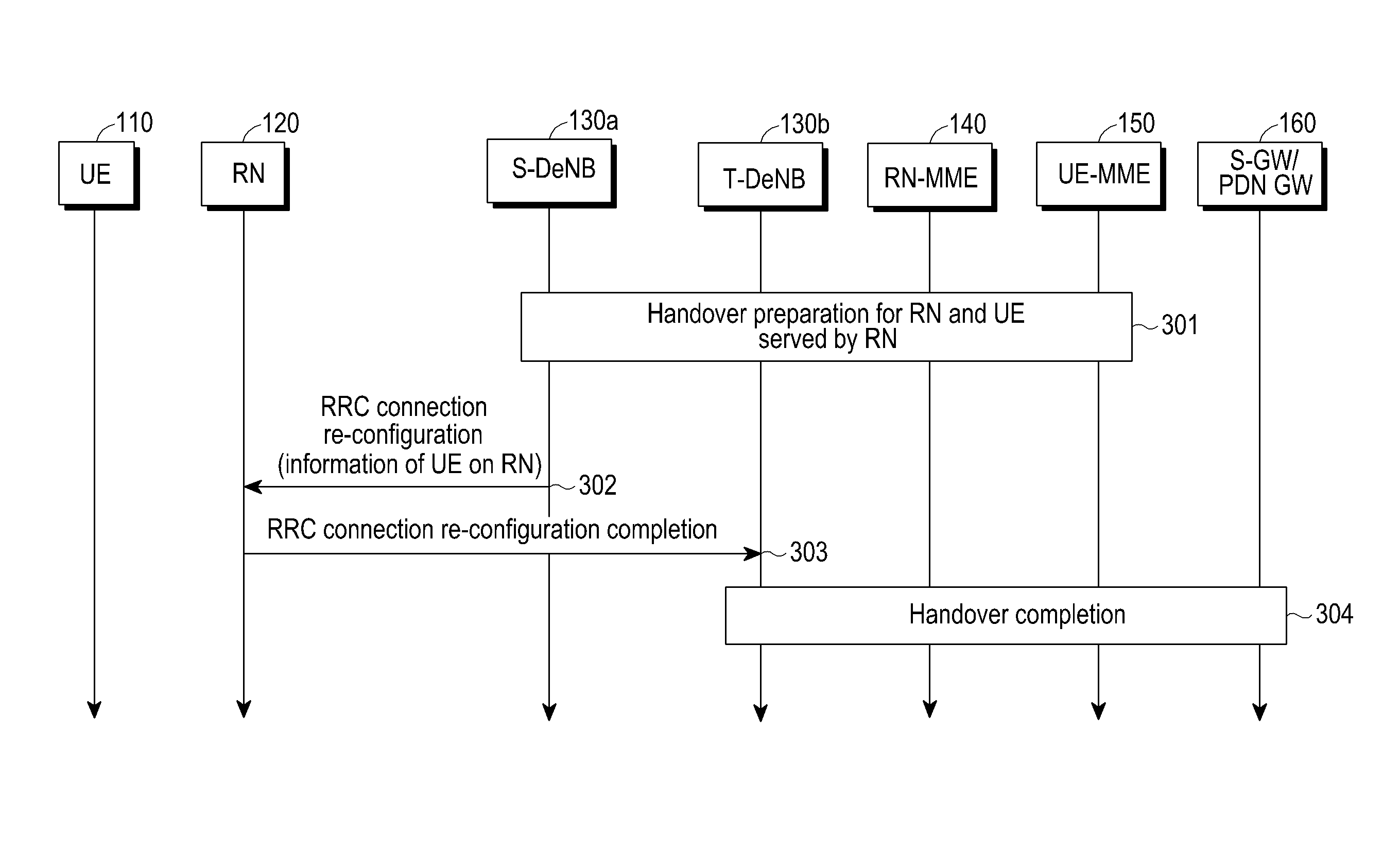
[0135]FIG. 3 is a flow diagram of supporting group handover according to an embodiment of the present disclosure.

[0136]Referring to FIG. 3, an S-DeNB 130a triggers handover preparation processes for an RN 120 and a UE 110 served by the RN 120 in operation 301. During the handover preparation process, allocation for the RN resource by the T-DeNB 130b in a Un interface is completed. It is necessary to transmit the eNB UE 110 an S1 AP ID and / or an MME UE S1 AP ID of the UE 110 served by the RN 120 in the RN and the T-DeNB interfaces to the S-DeNB 130a. It is necessary to transmit the uplink TEID and transport layer address of the UE 110 served by the RN 120 allocated in the RN and the T-DeNB interfaces to the S-DeNB 130a.

[0137]In operation 302, the S-DeNB 130a sends an RRC connection re-configuration message to the RN 120. The message includes mobile control information of the RN 120 as the UE 110. The message further includes information of the UE 110 served by the RN 120. The inform...

embodiment two

[0146]In the process of movement of the RN 120, it is necessary to switch from a source base station S-DeNB 130a to a target base station T-DeNB 130b, and this embodiment provides handover procedures of the RN 120 and the UE 110, ensures the continuity of service of the UE 110 served by the RN 120, and reduces handover signaling. An explanation and description of operations that are irrelevant to the present disclosure are omitted.

[0147]FIG. 4 is a flow diagram of supporting group handover according to an embodiment of the present disclosure.

[0148]Referring to FIG. 4, the S-DeNB 130a decides to initiate handover of the RN 120. The S-DeNB 130a switches the UE 110 served by the RN 120 to the T-DeNB 130b at the same time. The S-DeNB 130a sends a handover required message to the MME of the RN 120 (i.e., RN-MME 140). The handover required message includes all the existing information of the RN 120 as the UE 110. That is, information of the UE 110 is included in the existing handover requ...

embodiment three

[0181]In the movement process of the RN 120, it is necessary to switch from a source base station S-DeNB 130a to a target base station T-DeNB 130b. This embodiment provides handover procedures of the RN 120 and the UE 110, ensures the continuity of service of the UE 110 served by the RN 120 and reduces handover signaling.

[0182]This embodiment differs from embodiment one in that, in embodiment one, re-location of the MME of the RN 120 and of the MME of the UE 110 does not occur. In this embodiment, re-location of the MME of the RN 120 and the MME of the UE 110 occurs. The method of this embodiment is also used in the case that there is only re-location of the MME of the RN 120 or that there is only re-location of the MME of the UE 110, or that there is only re-location of part of the MME of the UE 110. In this embodiment, the source MME of the RN (e.g., the S-RN-MME 140a) selects a target MME (e.g., the T-UE-MME 150b) for the UE 110.

[0183]FIG. 5 is a flow diagram of supporting group ...


PUM


Abstract

A method supporting group handover, which is applied to a User Equipment (UE) in communication with a network via a Relay Node (RN), is provided. The method includes a base station (e.g., an S-DeNB) hands over an RN to a base station (e.g., a T-DeNB) and the S-DeNB hands over the UE served by the RN to the T-DeNB, wherein the handovers are performed simultaneously or separately. The various embodiments of the present disclosure provide a base station supporting group handover. The technical scheme set forth in the present disclosure can reduce an unnecessary signaling procedure, the possibility of network congestion, and can reduce the signaling procedure of handover when group handover occurs, so as to reduce the failure of the handover process and enhance the continuity of service.

Description

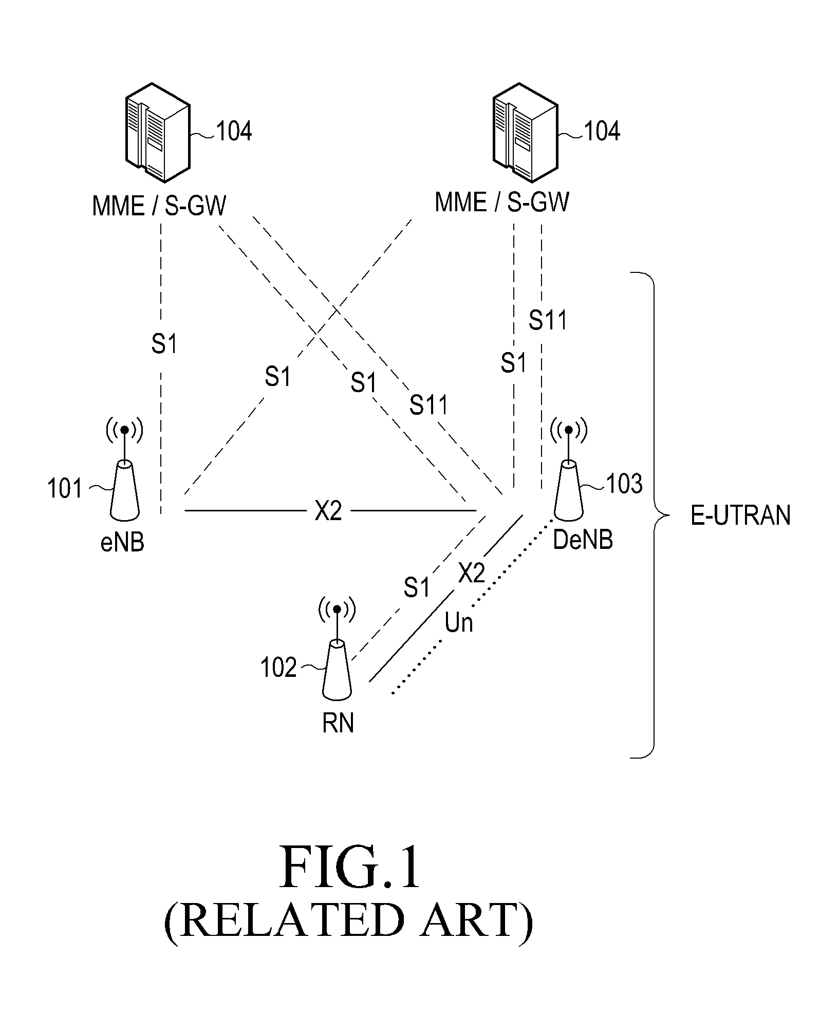
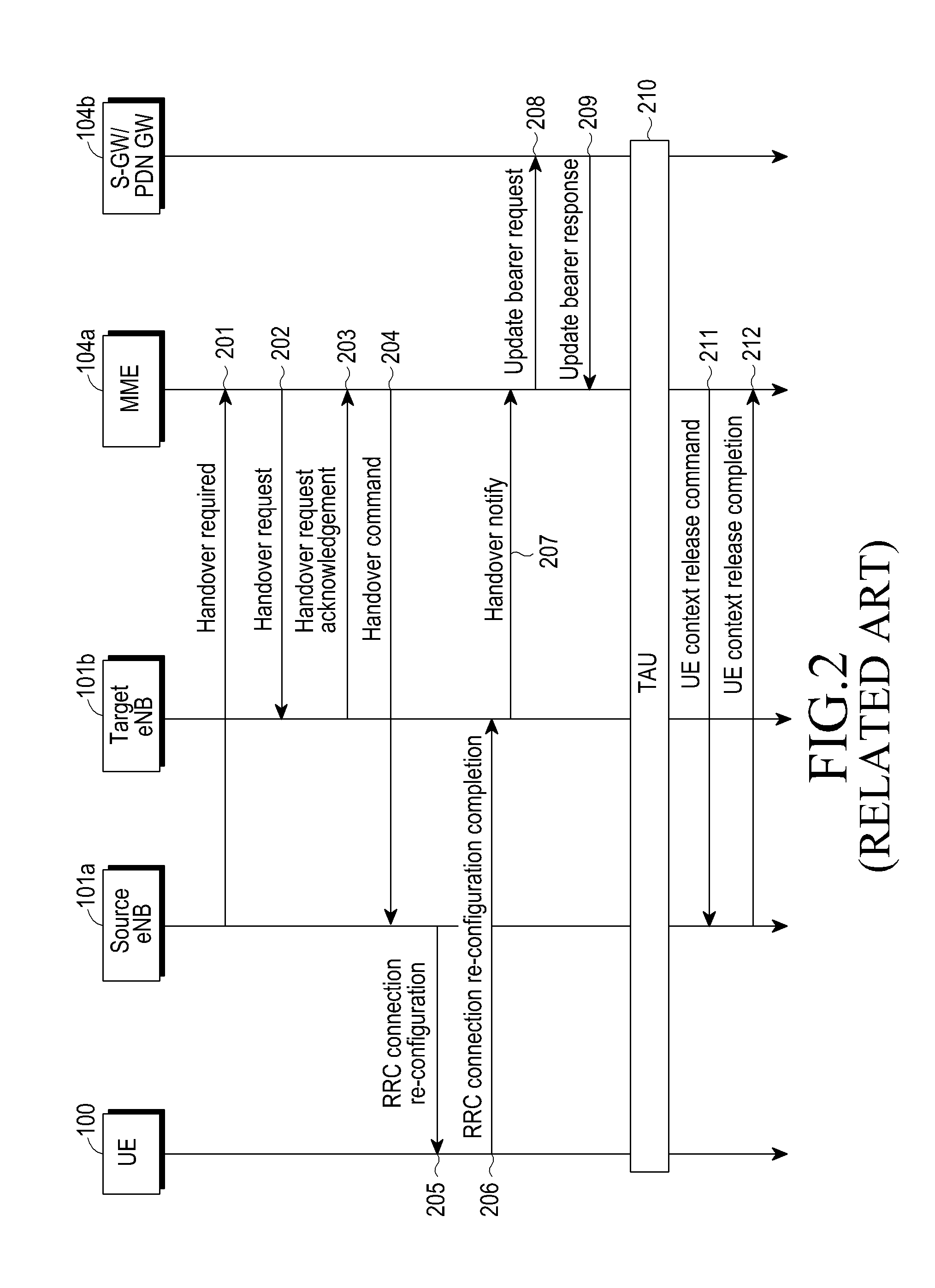
CROSS-REFERENCE TO RELATED APPLICATION(S)[0001]This application is a U.S. National Stage application under 35 U.S.C. §371 of an International application filed on Nov. 5, 2012 and assigned application number PCT / KR2012 / 009241, which claimed the benefit of Chinese patent applications filed on Nov. 4, 2011 and Jul. 13, 2012 in the Chinese Intellectual Property Office and assigned Serial numbers 201110346105.9 and 201210244886.5 respectively, the entire disclosure of each of which is hereby incorporated by reference.TECHNICAL FIELD[0002]The present disclosure relates to a mobile communications system. More particularly, the present disclosure relates to a method and device for supporting group handover in a mobile communications system.BACKGROUND ART[0003]FIG. 1 is a schematic diagram of a Long Term Evolution (LTE) system including supporting Relay Nodes (RN) according to the related art.[0004]Referring to FIG. 1, a wireless resource management entity includes a macro base station (i.e...

Claims


Application Information

Patent Timeline
Patent Type & Authority Patents(United States)
IPC IPC(8): H04W36/00H04W40/36H04W8/18
CPCH04W36/0072H04W36/0055H04W40/36H04W8/186H04W36/0009
Inventor XU, LIXIANGWANG, HONG
Owner SAMSUNG ELECTRONICS CO LTD
Learn More