Method and measuring system for determining deformations of a geometric body with the aid of force measuring sensors or deformation measuring sensors

a technology of force measurement and geometric body, applied in the direction of force measurement by elastic gauge deformation, measurement/indication equipment, instruments, etc., can solve the problems of defective machining of workpieces, loss of quality, and machining tool trajectories, and achieve precise force measurement and deformation detection.

Active Publication Date: 2016-12-13
PRO MICRON GMBH
View PDF5 Cites 6 Cited by
  • Summary
  • Abstract
  • Description
  • Claims
  • Application Information

AI Technical Summary

Benefits of technology

[0008]In light of this known prior art, the object of the present invention is to further refine a method of the aforementioned kind in order to enable a more precise detection of deformations of the geometric body and a more precise measuring of forces or torques acting upon the geometric body. Another aspect of the object to be achieved with the invention is to specify a corresponding measuring system, which, based on the prior art, is further refined for achieving the specified aim.
[0019]In the bridge circuit used in a preferred embodiment variant according to the invention, in particular, at least eight force sensors or deformation sensors are provided, of which in each case four belong to the first group and an additional four belong to the second group, wherein in such case these force sensors or deformation sensors, each four in number, are combined to form a bridge circuit, and the bridge circuits with their output signals are then included in the evaluation. This makes it possible to obtain a significantly finer detailed image of the forces or torques bearing on the geometric body, and the deformations caused by corresponding forces or torques. Such a correspondingly refined image brings significant improvements to the various applications. Thus, in the case of applications, as described in EP 1 889 685 A1, it is possible to detect more precisely disruptions of a planar and symmetrical clamping of a tool or workpiece in the spindle head, and to issue appropriate warnings or alarm signals. In an application as described in EP 2 103 379 A1, in which forces and torques occurring on the tool or on the tool holder during a machining process are recorded for the purpose of process monitoring and, optionally, process control, it is possible to more precisely assess the recorded values with respect to potential faulty measurements or artifacts, such that a more precise and accurate image is obtained.
[0021]One possibility for interconnecting the signal outputs of the force sensors or deformation sensors in electrical bridge circuits is to interconnect each of the four force sensors or deformation sensors of a group with their signal outputs to form an electrical bridge circuit, and then to evaluate the output signals of the at least two electrical bridge circuits in a way that suggests forces or torques which deviate from a symmetrical application of force or torque on the, in particular, symmetrically shaped, geometric body, or in order thereby to identify forces and torques or deformations which deviate from a symmetrical deformation of the, in particular symmetrically shaped, geometric body. In this case, the force sensors or deformation sensors of the respective group, in particular, are distributed in a regularly spaced configuration, in particular in a symmetrical configuration, along the geometric body, in order to thereby identify corresponding irregularities and asymmetries in the force effect or torque effect or in the deformation of the body. In this case, an appropriate evaluation is always carried out taking into account at least two (independent) spatial directions, so that, for example, not only axial components, but radial components as well, for example, may be taken into account. The result is a significantly more precise and accurate monitoring option, when such asymmetries with respect to acting forces or torques or with respect to deformations are also identified, which may not manifest in one spatial direction, but in another spatial direction instead. In the context of an application, as disclosed in EP 1 889 685 A1, for example, this means that it is possible to detect more precisely and accurately even the smallest disruptions in the correct and symmetrical retention of a tool or workpiece in the spindle head, and the system is able to issue an alarm.
[0023]Since the method according to the invention is frequently employed for measuring forces, torques imposed, or for deformations effected, on a geometric body in systems having rotating geometric bodies, in particular geometric bodies rotating about a rotation axis, but in other cases as well, in which corresponding symmetries in the system result, the force sensors and deformation sensors are frequently configured in such a way that a first group is arranged along the axial preferred direction of the body, which may, for example, extend along its rotation axis, a second group is arranged along a circle line drawn around this preferred axis, thus, along a circular spatial direction. A particularly simple and elegant evaluation of the measurement data obtained is then achieved if, in accordance with the coordinate system considered herein, the signal curves are output in polar coordinates or in cylindrical coordinates, in particular, are graphically displayed, for example, recorded once again over a time axis.

Problems solved by technology

Such a faulty clamping, as described in the publication, results in trajectories of the machining tool that deviate from the set trajectory, and thus to a defective machining of the workpiece, ultimately to losses in quality and finally to rejection.
One problem in connection with the methods and measuring systems disclosed in the aforementioned publications is that distorted measurement results may frequently occur due to imprecise knowledge about the orientation of the acting forces and torques, or about components thereof, or of the direction of deformation along different coordinate directions.
Thus, for example, when monitoring forces or torques, as is described in EP 2 103 379 A1, it is impossible to distinguish in different situations between actual measurement values and system error-related artifacts.
If differences arise, a corresponding error message may then be issued during the course of the process, or the corresponding measuring system may generate such an error message.
For then, unpredicted irregularities and events could have occurred, for example, the failure of an expected tool cutter or else a system artifact at a different location.

Method used


Image

  • Method and measuring system for determining deformations of a geometric body with the aid of force measuring sensors or deformation measuring sensors
  • Method and measuring system for determining deformations of a geometric body with the aid of force measuring sensors or deformation measuring sensors
  • Method and measuring system for determining deformations of a geometric body with the aid of force measuring sensors or deformation measuring sensors

Examples


Embodiment Construction

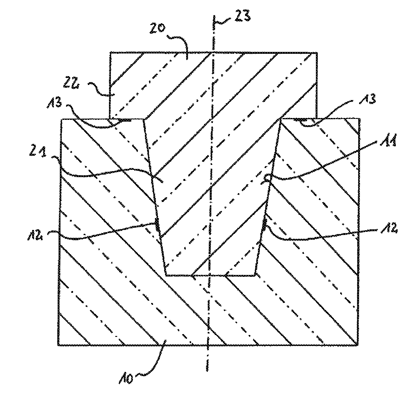
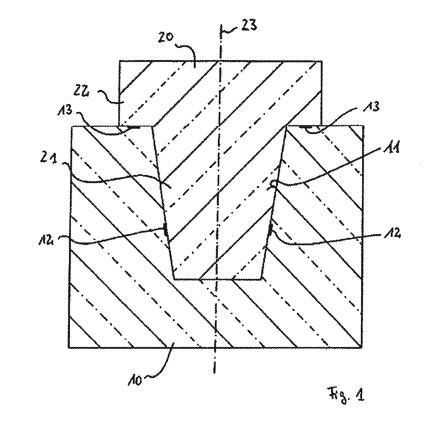
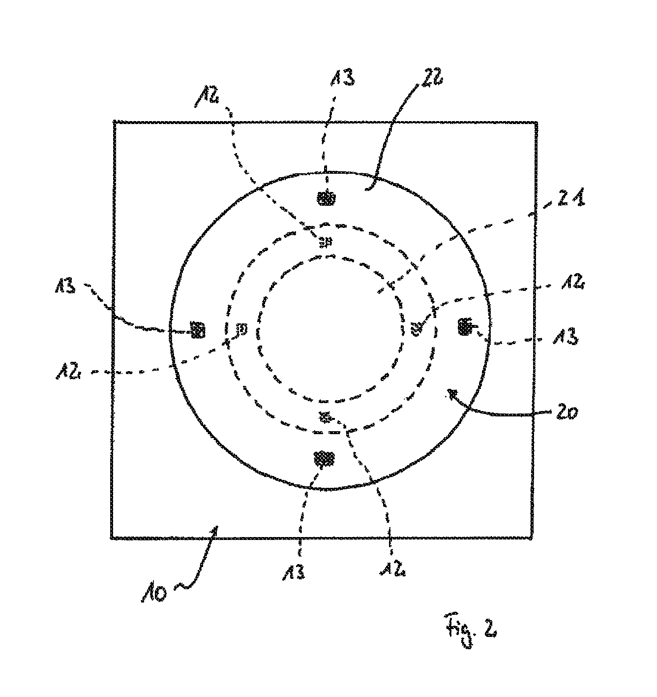
[0030]FIG. 1 schematically shows a sectional view through a configuration of two bodies 10, 20, one form-fitted inside the other. The body 10 includes a conical holder 11 integrated in the body, in which a corresponding, conical connection piece 21 of the body 20 is inserted. The body 20 also includes a collar 22, which extends laterally beyond the connection piece 21. As is apparent, in particular, in FIG. 2, the body 20 is rotationally symmetrical in design about its longitudinal axis 23 with a circumferential, projecting collar 22.

[0031]First, force sensors 12 are arranged in the interior of the holder 11 at the same level perpendicular to the longitudinal axis 23 of the body 20, in such a way that they are able to register forces transmitted from the connection piece 21 to the surface of the holder 11, which act perpendicular to the boundary surfaces. As is apparent in FIG. 2, a total of four such first force sensors 12 are arranged in this exemplary embodiment, in each case at ...


PUM

PropertyMeasurementUnit
forcesaaaaaaaaaa
torquesaaaaaaaaaa
force measuringaaaaaaaaaa

Abstract

A method for ascertaining deformations of a geometric body or for measuring forces or torques acting thereon using force measuring sensors or deformation measuring sensors. A plurality of such sensors are arranged on the geometric body in at least two groups. A first group of sensors registers forces acting on the geometric body or deformations of the geometric body in a first spatial direction with reference to a coordinate system fixed relative to the geometric body. A second group of sensors registers forces acting on the geometric body or deformations thereof in a second spatial direction with reference to the coordinate system fixed relative to the geometric body, which is independent of the first spatial direction. Signal outputs of the sensors are compared to one another for the purpose of registering and evaluating signals and for determining or assessing force components or deformation components acting in different spatial directions.

Description

BACKGROUND OF THE INVENTION[0001]Technical Field[0002]The invention relates to a method for determining deformations of a geometric body and a method for measuring forces or torques acting on a geometric body with the aid of force measuring sensors or deformation measuring sensors. The invention also relates to a corresponding measuring system.[0003]Background Information[0004]In a wide variety of technical applications, information on forces or torques, which act on a body, for example, a tool or a work piece or a tool holding device or the like, or information on deformations of the body caused by corresponding forces or torques, constitute important parameters, which are measured and / or monitored. Thus, applications are known, for example, in which corresponding force sensors or deformation sensors are used to check the correct planar contact and clamping of a tool in a spindle head of a working spindle of a processing machine. Such a method and corresponding monitoring device ar...

Claims


Application Information

Patent Timeline
Patent Type & Authority Patents(United States)
IPC IPC(8): G01L1/04G01L5/00G01L5/16G01L3/10G01L1/00
CPCG01L5/16G01L1/005G01L3/108G01L5/0004G01L5/0076B23Q17/005B23Q17/0966
Inventor WULFF, KOLJA
Owner PRO MICRON GMBH
Why Eureka
Try Eureka