Portable cockpit yoke assembly

a cockpit yoke and portable technology, applied in the field of portable cockpit yoke assembly, can solve the problems of novice or inexperienced model planes, large and complex design of the apparatus and console, and cannot be portable nor adapted to be carried by hand, so as to improve the operation of the model airplane. , the effect of positive and improving the operation

Inactive Publication Date: 2016-12-20
BOWERS RICHARD A
View PDF22 Cites 2 Cited by
  • Summary
  • Abstract
  • Description
  • Claims
  • Application Information

AI Technical Summary

Benefits of technology

[0008]In view of the foregoing, it is a primary objective of the subject invention to eliminate a direct contact of a pair of joysticks on a standard RC receiver by the thumb and fingers of a model plane pilot and provide a positive and improved operation of a model airplane.
[0009]Another object of the invention is the cockpit yoke assembly is lightweight, portable and can be quickly and easily mounted on top of a standard RC Transmitter with mechanical linkage adapted for attachment to the transmitter's two joysticks.

Problems solved by technology

These apparatus and console are large and complex in design and similar to an actual aircraft flight simulator used for training commercial and military pilots.
Also, the prior art simulator-like apparatus are floor mounted, they are not portable nor are they adapted to be hand carried and mounted on top of a standard RC transmitter.
A key problem with operating the two joysticks is a novice or inexperienced model plane pilot will often move, for example, the left joystick with his or her thumb and cause the plane to speed up or slow down and then inadvertently slip into turning the plane's direction at virtually the same time.
Also, the pilot will often move the right joystick with his or her thumb and cause the plane to climb or descend and then inadvertently slip into banking the plane at virtually the same time.

Method used


Image

  • Portable cockpit yoke assembly
  • Portable cockpit yoke assembly
  • Portable cockpit yoke assembly

Examples


Embodiment Construction

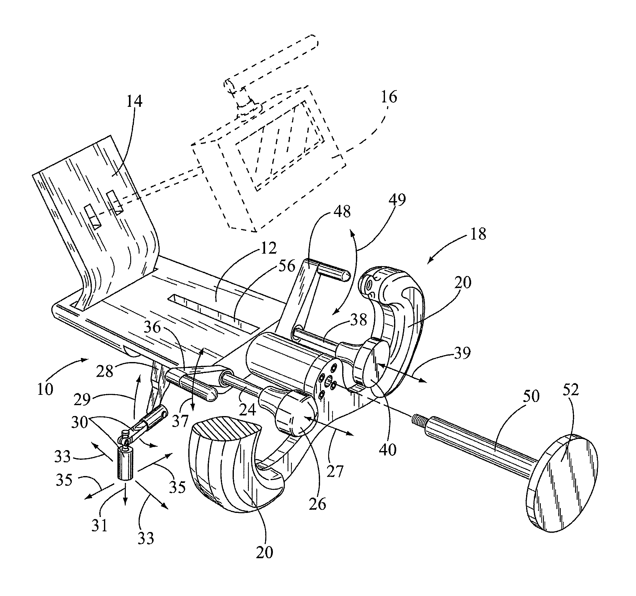
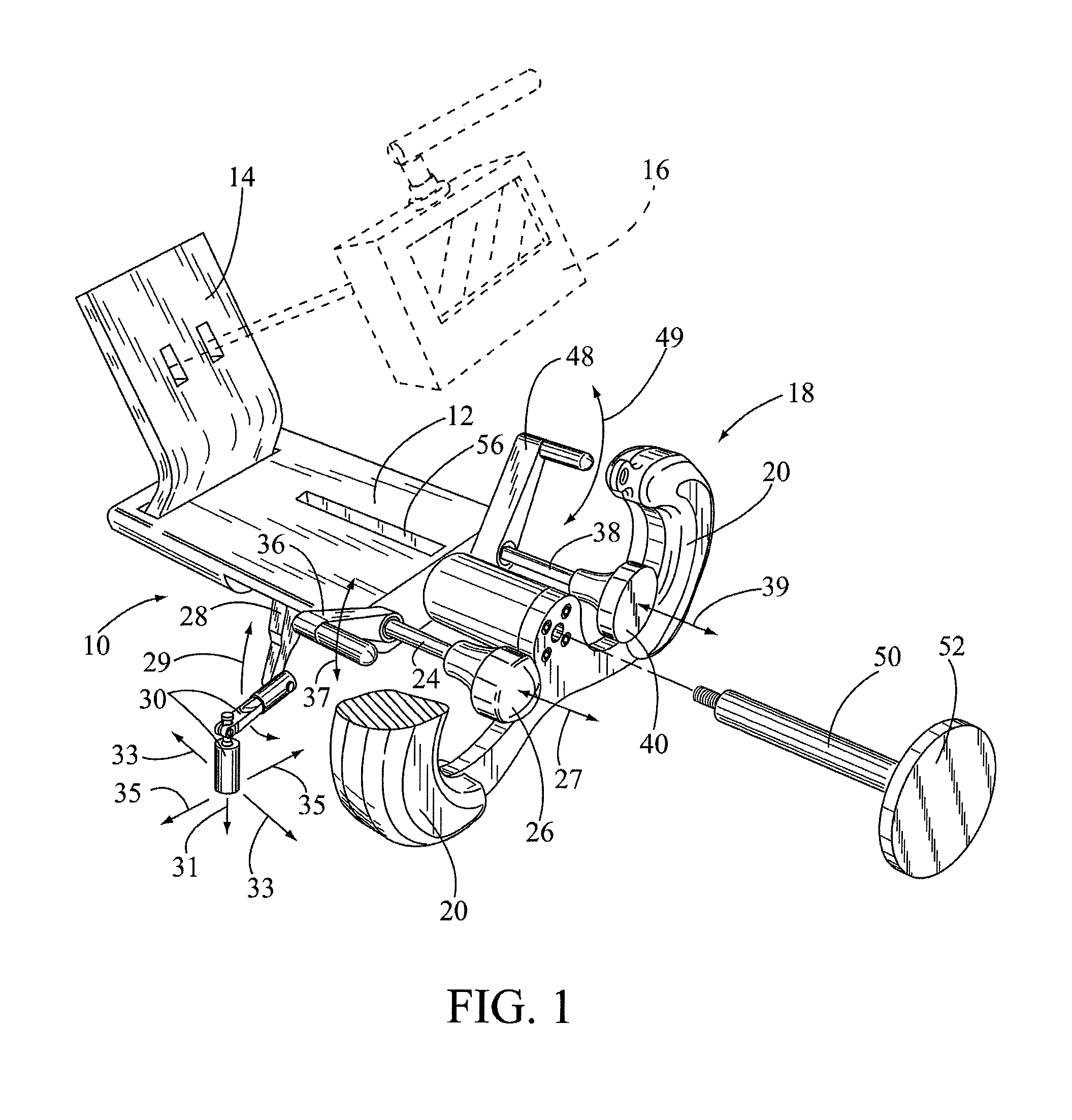
[0020]In FIG. 1, the portable cockpit yoke assembly is shown having general reference numeral 10. The yoke assembly 10 includes a yoke body 12 with an upwardly extending dashboard 14. The dashboard 14 can be used for mounting an electronic telemetry unit 16 thereon. The telemetry unit 16 is shown in dashed line. The telemetry unit 16 is used for keeping track of a model airplane during flight. The model airplane isn't shown in the drawings.

[0021]Mounted in front of the yoke body 12 is a hand grip, having general reference numeral 18. The hand grip 18 includes a pair of hand grip handles 20, which are held by a model airplane operator or pilot 22. The pilot 22 is shown in dashed lines in FIG. 4. The hand grip 18 is stationary and is not used for controlling the model airplane. A portion of the left hand grip handle 20 has been cutaway to help illustrate the controls of the yoke assembly 10.

[0022]A horizontal, first control arm 24 is slidably mounted, as indicated by arrow 27, in the ...


PUM


Abstract

A cockpit yoke assembly adapted for mounting on top of a RC transmitter for controlling the operation of a model airplane. The yoke assembly includes a first control arm with a throttle knob. The first control arm is attached to a first ball and socket linkage adapted for attachment a first joystick on the transmitter. A rudder control lever is attached to the first control arm. The yoke assembly includes a second control arm with an elevator knob. The second control arm is attached to a second ball and socket linkage adapted for attachment to a second joystick on the transmitter. An aileron control lever is attached to the second control arm. The first and second ball and socket linkage are used for moving the first and second joysticks fore or aft and left or right during the operation of the model airplane.

Description

[0001]This application is a continuation patent application based on a non-provisional patent application having a Ser. No. 13 / 466,577, filed on May 8, 2012, by the subject inventor, and having a title of “Portable Cockpit Yoke Assembly for mounting on a Radio Controlled Transmitter used with a Model Airplane.”BACKGROUND OF THE INVENTION[0002](a) Field of the Invention[0003]This invention relates to a mechanical device for an operation of a standard radio controlled transmitter or RC transmitter used for controlling a model airplane during take off, in flight and landing, and more particularly, but not by way of limitation, to a portable, cockpit yoke assembly adapted for mounting on top of the RC transmitter. The yoke assembly provides for positive control of the airplane and eliminates a model airplane operator or pilot using his or her thumbs for operating a pair of joysticks on the RC transmitter.[0004](b) Discussion of Prior Art[0005]In U.S. Pat. No. 4,386,914 to Dustman, U.S. ...

Claims


Application Information

Patent Timeline
Patent Type & Authority Patents(United States)
IPC IPC(8): A63H27/00B64C13/04G05G1/10
CPCB64C13/04G05G1/10B64C2203/00A63H30/04B64C13/0423
Inventor BOWERS, RICHARD A.
Owner BOWERS RICHARD A
Why Eureka
Try Eureka