Suppression method for strong interference noise of carrier channel of power line and circuit structure thereof

a carrier channel and strong interference technology, applied in the field of strong interference noise suppression of carrier channel of power line and the circuit structure thereof, can solve the problems of serious mismatching of carrier signal impedance, weak transmission signal power actually transmitted in power line, and inability to design a larger output power of carrier communication equipment, etc., to achieve accurate distinction, effectively suppress strong noise interference, and improve the signal-to-noise ratio of transmission carrier

Active Publication Date: 2016-12-20
SHENZHEN HUAZHI HIGH TECH CO LTD
View PDF8 Cites 0 Cited by
  • Summary
  • Abstract
  • Description
  • Claims
  • Application Information

AI Technical Summary

Benefits of technology

[0008]In order to solve the above technical problem, a suppression method for strong interference noise of power line carrier channel and its circuit structure is designed in this invention. This method is based on the frequency scope of strong interference noise and carrier in carrier channel, distributes and transmits the interfered carrier signal into corresponding matched noise suppression circuit, so as to conduct the extraction and enhancement of strong interference noise suppression and weak carrier signal, thereby effectively realizing the strong interference noise suppression in power line carrier channel.
[0010]A. The carrier signal extracted from the receiving point is introduced into the high-pass filter, eliminating the interference signal within lower limit of frequency interval mixed in carrier signal, so as to obtain the mixed signal higher than lower limiting value of frequency interval, which mixes strong interference noise signal and carrier signal;
[0017]The beneficial effects of this invention are: 1. Regardless of any random change in power line carrier channel, the frequencies of strong interference noise and carrier (sub-carrier) can be accurately distinguished, and the carrier (sub-carrier) signal damaged by strong interference noise can be transmitted to corresponding processing circuit for suppression; in the major premise of whole carrier frequency band not being suppressed, the weak carrier (sub-carrier) signal can effectively attenuate the strong interference noise, that is, the frequencies of strong interference noise and weak carrier are not necessary for measurement, the frequency of strong interference noise is higher or lower than carrier frequency can be accurately distinguished through specifically distinguishing the level output of circuit, thereby precisely guiding the carrier signal damaged by strong interference noise to corresponding suppression circuit, so as to effectively suppressing the strong noise interference; 2. The frequency scope of power line carrier channel regulated by China is: from 40 khz to 500 khz, therefore, any strong interference noise suppression circuit designed by this invention method satisfies conditions of normal work in this frequency band; 3. For any mixed signal with difference of 50 dB, it is based on suppression of strong interference signal, however, the weak signal can't be compressed and attenuated. The design difficulty can be imagined to distinguish or screen out the weak carrier signal from noise inundation with amplitude of 50 dB by “simulative” or “digital” processing technology. This invention method first starts from distinguishing, recognizing, and suppressing the strong interference noise signal, although the weak carrier signal can't be caught, however the carrier (sub-carrier) absolutely won't be weakened or compressed. When the strong noise interference is suppressed to certain level, the carrier signal will be extracted for effective amplification, thereby improving the signal to noise ratio of transmission carrier (sub-carrier) signal in channel.

Problems solved by technology

The transmission of carrier signal in power line transporting electric energy has the problem of seriously mismatched impedance.
Therefore, it is impossible to design larger output power of carrier communication equipment, and the carrier signal power actually transmitted in power line is very weak.
However, it will be a very difficult job to directly separate and measure it through dedicated circuits or instruments.
Although the strongly interfered carrier signal actually transmitted in power line is very complicated, and is impossible to be predicted or difficult to be specifically described with a stable signal, in consideration of principle that any complicated signal can be decomposed into a variety of sine wave signals with different frequencies and different amplitudes according to Fourier transformation, we can simplify the carrier signal actually transmitted in power line and damaged by strong interference noise or pulse into the superposition of two lists of sine wave signals with amplitude difference of 50 dB and different frequencies.
However, when swapping frequencies of strong and weak sine waveforms, the strong sine wave signal is improved and enhanced on the contrary, and the weak sine wave signal is suppressed, thereby getting the opposite results.

Method used


Image

  • Suppression method for strong interference noise of carrier channel of power line and circuit structure thereof
  • Suppression method for strong interference noise of carrier channel of power line and circuit structure thereof
  • Suppression method for strong interference noise of carrier channel of power line and circuit structure thereof

Examples


Embodiment Construction

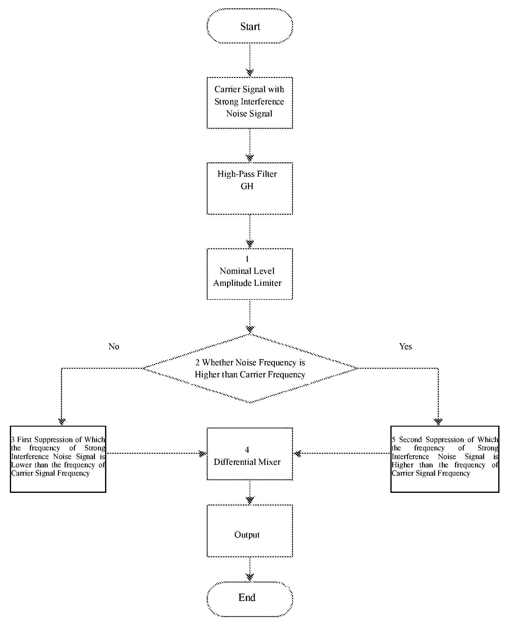
[0029]A suppression method for strong interference noise of power line carrier channel is based on the processing process to carrier signals transmitted in standardized frequency interval among power line transmission regional area, which is important in that: steps of the method described by FIG. 1, comprise:

[0030]A. The carrier signal extracted from the receiving point is introduced into the high-pass filter (GH), eliminating the interference signal within lower limit of frequency interval mixed in carrier signal, so as to obtain the mixed signal higher than lower limiting value of frequency interval, which mixes strong interference noise signal and carrier signal;

[0031]B. The mixed signal is conducted with amplitude limiting through a nominal level amplitude limiting circuit 1, so as to obtain the mixed amplitude limiting signal within nominal level range;

[0032]C. The mixed amplitude limiting signal is introduced into a time-sharing processing channel module 2, which includes a c...


PUM


Abstract

A suppression method for strong interference noise of power line carrier channel is based on the processing process to carrier signals transmitted in standardized frequency interval among power line transmission regional area. According to the situation of frequency lead or lagging carrier of strong interference noise, the pending signals are respectively transmitted to a first suppression circuit (3) of which the frequency of strong interference noise signal is lower than the frequency of carrier signal, and a second suppression circuit (5) of which the frequency of strong interference noise signal is higher than the frequency of carrier signal through split-flow processing channel module to process the amplitude limiting signal, and then output signals of the first suppression circuit (3) and second suppression circuit (5) are conducted with differential mixing and output to complete the noise reduction process. Regardless of any position of strong interference noise and carrier in channel, the suppression of strong interference noise of power line can be realized by this method. In the major premise of the weak carrier signal not being suppressed, this method has realized that the strong interference noise is effectively attenuated.

Description

RELATED APPLICATIONS[0001]The instant application is the U.S. National Phase under 35 U.S.C. §371 of International Application No. PCT / CN2013 / 079599 entitled SUPPRESSION METHOD FOR STRONG INTERFERENCE NOISE OF CARRIER CHANNEL OF POWER LINE AND CIRCUIT STRUCTURE THEREOF, filed Jul. 18, 2013, designating the U.S.; which claims priority to Chinese Patent Application No. 201310203457.8, filed May 28, 2013, now Chinese Patent No. CN103338080. The contents of these related applications are herein expressly incorporated by reference in their entireties.FIELD OF THE INVENTION[0002]This invention belongs to the technology field of power line carrier communication, which relates to a suppression method for interfering noise in the process of communication by utilizing the power line carrier channel, specifically the suppression method for strong interference noise of power line carrier channel and its circuit structure.BACKGROUND OF THE INVENTION[0003]The transmission of carrier signal in pow...

Claims


Application Information

Patent Timeline
Patent Type & Authority Patents(United States)
IPC IPC(8): H04B15/00H04B3/54
CPCH04B3/54H04B15/00H04B2203/5425
Inventor XU, ZHONGYIXU, HAIBO
Owner SHENZHEN HUAZHI HIGH TECH CO LTD
Why Eureka
Try Eureka