Micro-architected materials for heat exchanger applications

a heat exchanger and micro-architecture technology, applied in the field of heat exchangers, can solve the problems of further complicated problems, limited to a single truss layer, and high cost of fabrication methods described

Active Publication Date: 2016-12-27
HRL LAB
View PDF7 Cites 15 Cited by
  • Summary
  • Abstract
  • Description
  • Claims
  • Application Information

AI Technical Summary

Problems solved by technology

The problem is further complicated if the Heat Exchanger has to support mechanical loads.
However, the only fabrication methods described are expensive, limited to a single truss layer, and limited to large truss unit cell sizes.
The structures described therein are constrained to simple, flat geometries, do not have enhancements for increased convective heat transport, and are not designed to satisfy multiple functions (e.g. structural function in addition to heat transfer function).

Method used


Image

  • Micro-architected materials for heat exchanger applications
  • Micro-architected materials for heat exchanger applications
  • Micro-architected materials for heat exchanger applications

Examples


Embodiment Construction

[0029]In the following detailed description, only certain exemplary embodiments of the present invention are shown and described, by way of illustration. As those skilled in the art would recognize, the described exemplary embodiments may be modified in various ways, all without departing from the spirit or scope of the present invention. Accordingly, the drawings and description are to be regarded as illustrative in nature, and not restrictive.

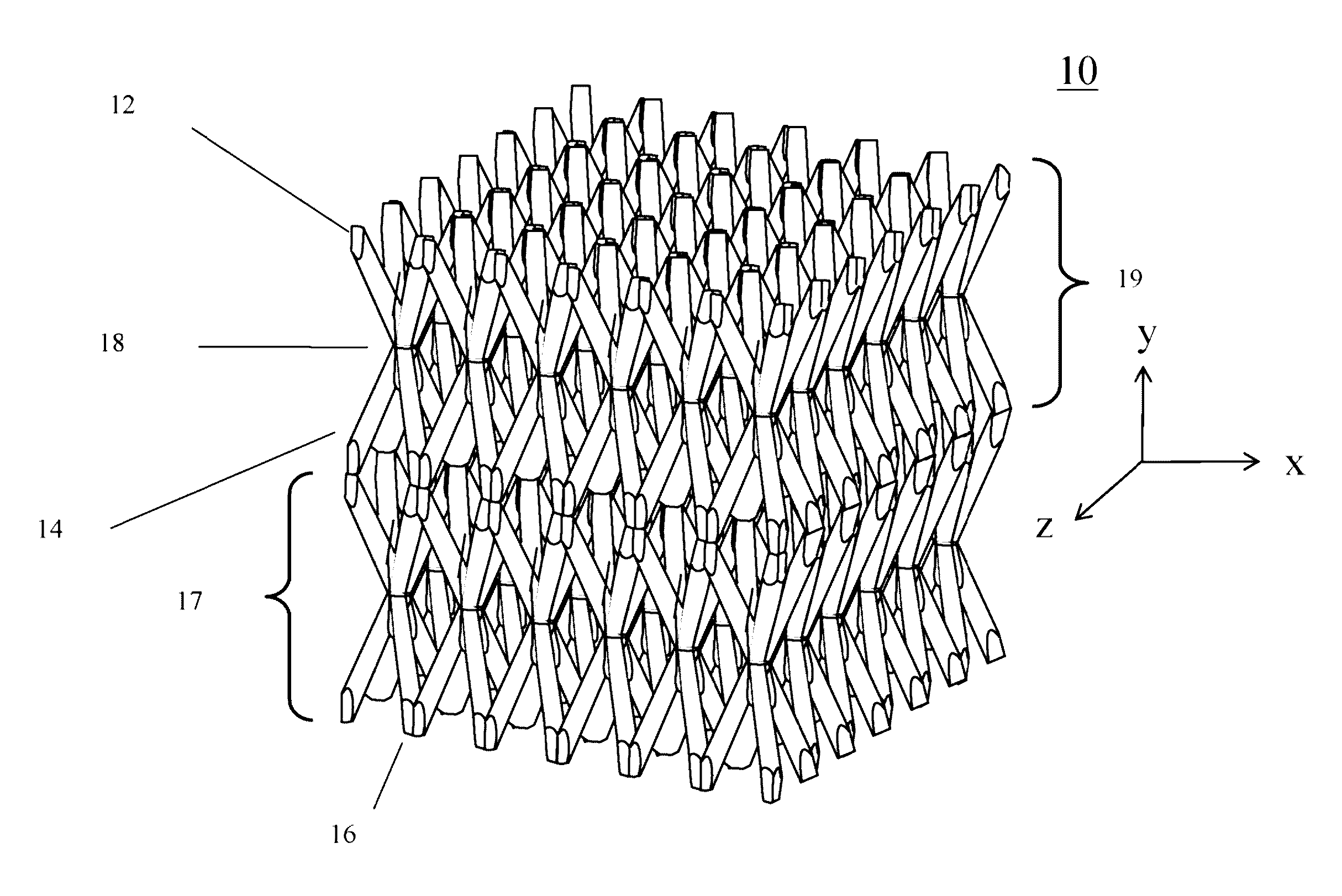
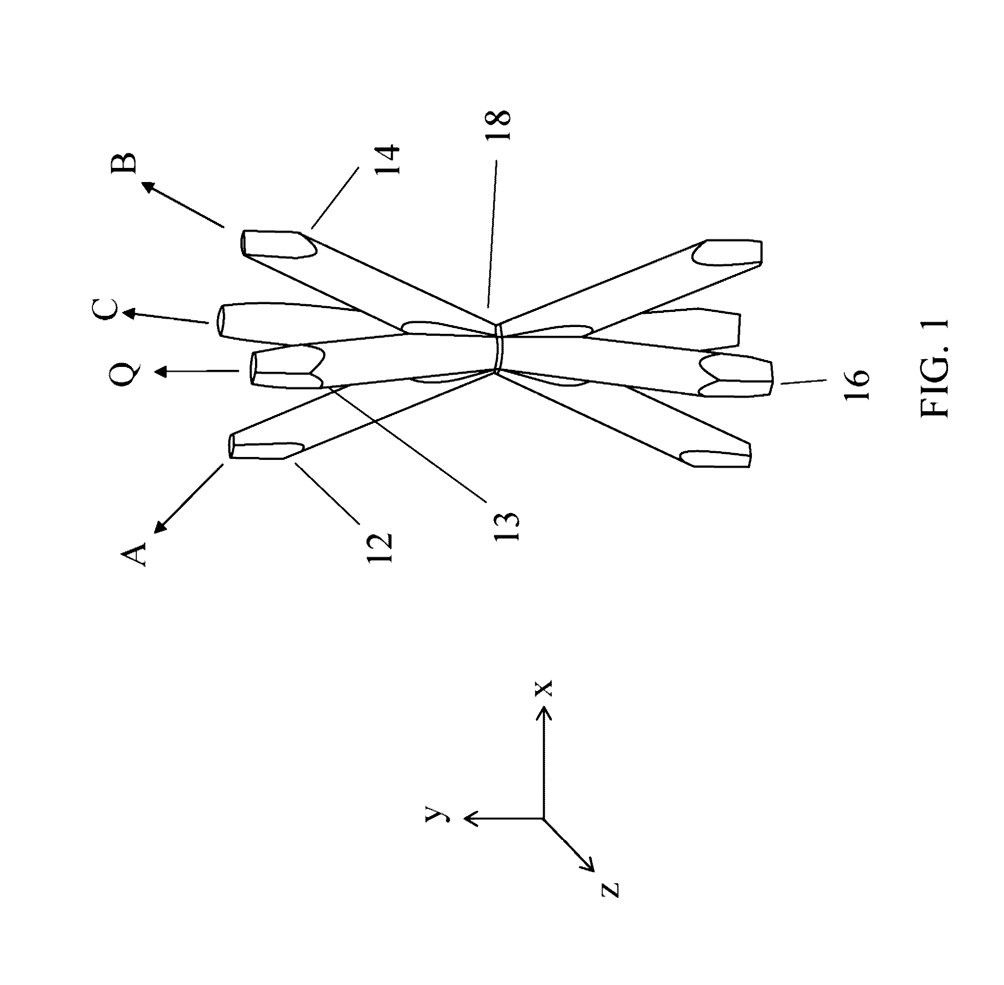
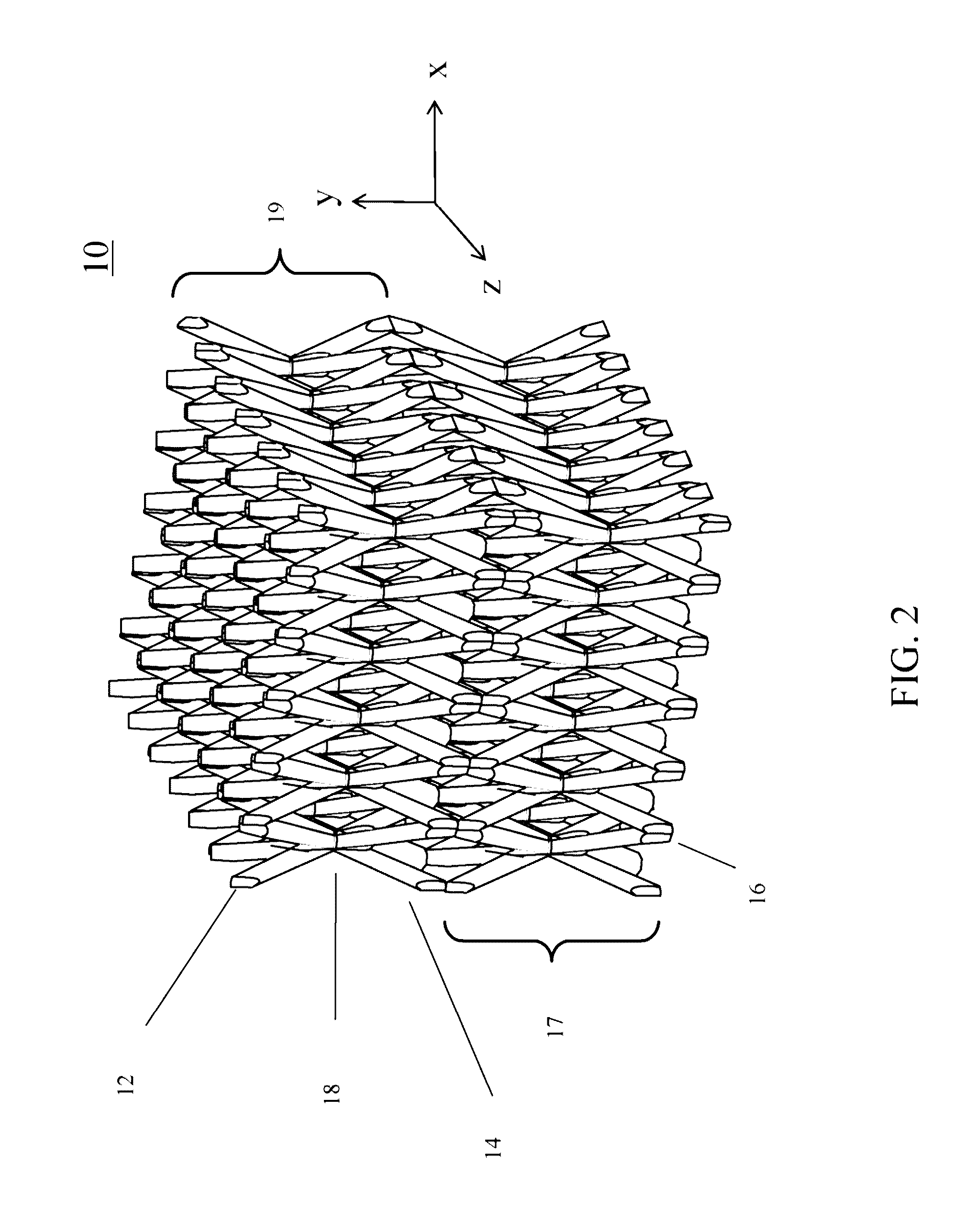
[0030]In the context of embodiments of the present invention, a three-dimensional ordered microstructure is referred to as an ordered three-dimensional structure at the micrometer scale, microstructure or as microtruss. In one embodiment of the present invention, a Heat Exchanger composed of a three-dimensional ordered microstructure is provided with hollow truss members. Here, the Heat Exchanger transfers heat from one fluid to another fluid through conduction and / or convection.

[0031]An alternative embodiment of the Heat Exchanger utilizes a...


PUM

PropertyMeasurementUnit
diameteraaaaaaaaaa
diameteraaaaaaaaaa
angleaaaaaaaaaa

Abstract

A method of exchanging heat between fluids with a heat Exchanger comprising a three-dimensional ordered microstructure material within a shell. The three-dimensional ordered microstructure material has dimensions that allow for large surface area to volume ratios, between 300 and 15000 m2 / m3. Alternatively the three-dimensional ordered microstructure may have an open volume fraction between 0.4 and 0.6. The three-dimensional ordered microstructure may be comprised of hollow truss elements and partially filled with a thermally conductive material or a fluid. The Heat Exchanger has a heat transfer coefficient multiplied by the surface area to volume ratio between 3.7*107 and 7*109 Watts per M3K.

Description

RELATED APPLICATIONS[0001]This application is a divisional application and claim priority to U.S. Ser. No. 12 / 506,014 filed Jul. 20, 2009 titled “MICRO-ARCHITECTED MATERIALS FOR HEAT EXCHANGER APPLICATIONS”FIELD OF THE INVENTION[0002]The present invention relates to the area of Heat Exchangers using conduction and or convection, and in particular, Heat Exchangers capable of supporting mechanical loads.BACKGROUND OF THE INVENTION[0003]Heat Exchangers transfer heat from a hot area to a cooler area through conduction and convection. Certain forms of Heat Exchangers use tubes within a shell. Other designs may use heat pipes.[0004]For a given amount of heat to transfer there is usually a minimum size of Heat Exchanger. In general, if more heat has to be transferred then a larger Heat Exchanger is needed or one that is more efficient. The amount of heat that may be transferred is the heat transfer coefficient multiplied by the surface area to volume ratio. Another figure of merit for the ...

Claims


Application Information

Patent Timeline
Patent Type & Authority Patents(United States)
IPC IPC(8): F28F9/00
CPCF28F9/00B29C64/129F28D7/0058F28D7/0066F28D7/1615F28D15/0275F28D15/04F28D15/046F28F1/124F28F3/022F28F2255/18F28F2260/02
Inventor ROPER, CHRISTOPHER S.CARTER, WILLIAM B.JACOBSEN, ALAN J.
Owner HRL LAB
Why Eureka
Try Eureka