

Use of location information in multi-radio devices for mmWave beamforming
a multi-radio device and beamforming technology, applied in the direction of polarisation/directional diversity, instruments, wireless communication, etc., can solve the problems of mmwave technology unsuitable for certain wireless applications, beamforming effort itself requires significant time and a certain amount of computing overhead to complete, and signals experience destructive interference. , to achieve the effect of faster and more efficient beamforming
- Summary
- Abstract
- Description
- Claims
- Application Information
AI Technical Summary
Benefits of technology
Problems solved by technology
Method used
Image

Examples
Embodiment Construction
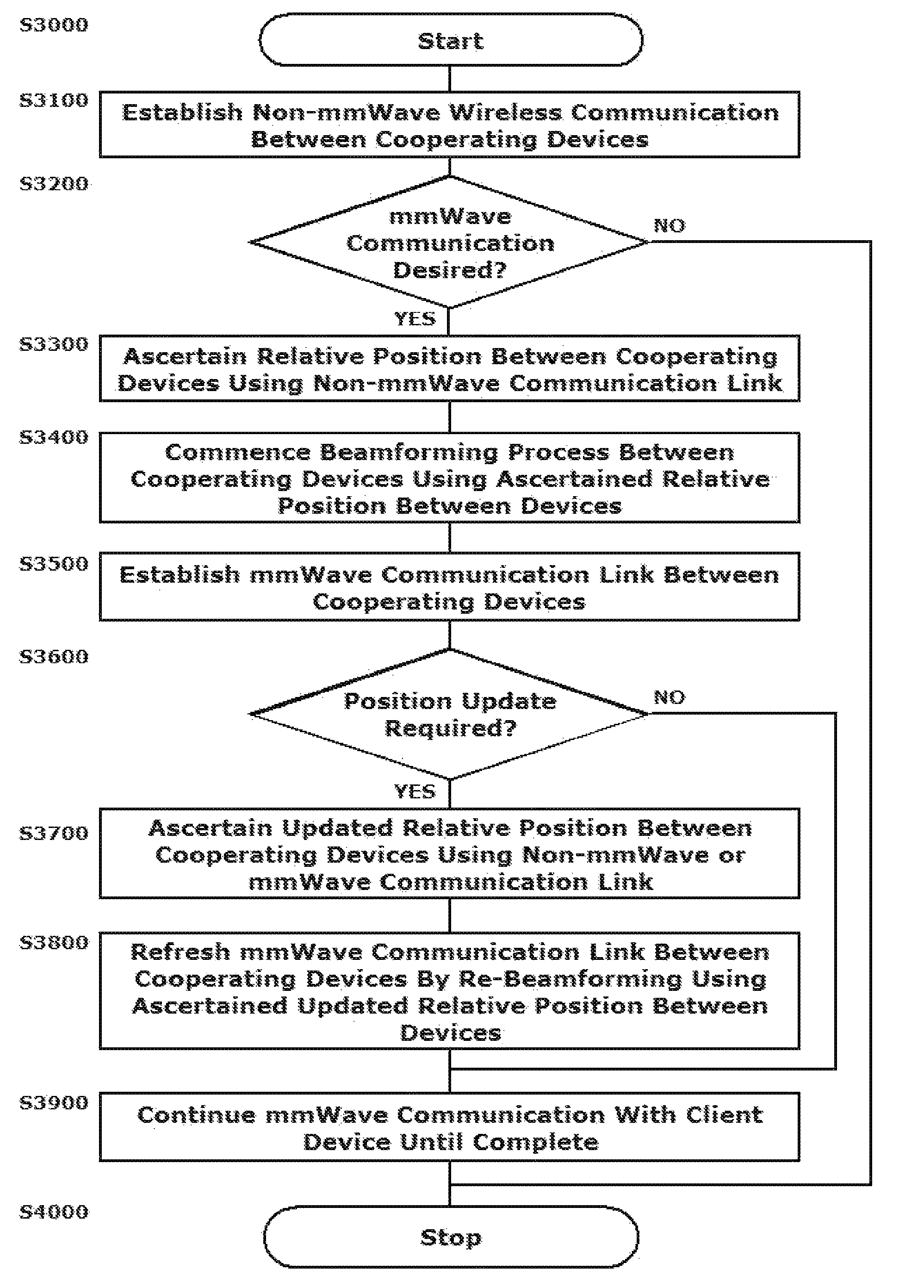
[0002]This disclosure relates to systems and methods for using location information derived from other radios in a multi-radio device to streamline a millimeter wave (mmWave) beamforming process.
[0003]2. Related Art
[0004]With the proliferation of wireless devices of all types running increasingly sophisticated applications, the demand for available bandwidth has increased dramatically. Communications in the millimeter wave (mmWave), e.g. 60 GHz region of the frequency spectrum have emerged as a unique solution to the need for increased bandwidth for a number of reasons. Transmitting, for example, in the 60 GHz frequency range offers extremely high data throughputs as a result of the ultra-wide bandwidth available. A tradeoff is that communications in this frequency range are highly directional with directional antenna beam forming arrays being required to sustain reasonable transmission distances based on the atmospheric absorption of the transmitted RF energy.
[0005]Wireless communi...
PUM
 Abstract
Description
Claims
Application Information