Method and apparatus for thermal exchange with two-phase media

a technology of thermal exchange and two-phase media, which is applied in the direction of domestic cooling apparatus, separation processes, instruments, etc., can solve the problems of high energy consumption, unfavorable thermal exchange, and high energy consumption, and achieves tight control, improved thermal exchange efficiency, and higher heat transfer coefficient

Active Publication Date: 2010-03-25
ADVANCED THERMAL SCI
View PDF14 Cites 27 Cited by
  • Summary
  • Abstract
  • Description
  • Claims
  • Application Information

AI Technical Summary

Benefits of technology

[0010]The PLM approach uses the two different phase states of the refrigerant in a uniquely integrated manner. The pressure of the suction line to the compressor is influenced by the mass of refrigerant received, since the compressor is a device that processes a fixed volume per unit of time. In the PLM system the flow through the thermal load has a smaller differential in temperature than would exist with unidirectional transport of fully mixed dual flows, and the thermal load temperature can be thus more tightly controlled. Essentially, the flow through the thermal load is so controlled as to be mainly or completely the cooled expanded component, and in consequence the pressure drop undergone by the refrigerant in passing through the load is lessened. Furthermore, by post load mixing after the refrigerant has passed through the load, the refrigerant passing through the thermal load has a greater percentage of liquid than if all the hot gas had been mixed before the load and thus has a higher heat transfer coefficient, so that thermal exchange is more efficient, particularly at and near th...

Problems solved by technology

Many such control systems also are required to change the temperature of the thermal load in accordance with process conditions, sometimes with great rapidity.
As one illustration, semiconductor manufacturing equipment and processes are often dependent upon temperature control of the wafers or other elements on which various surfaces are being deposited or etched, using techniques which are highly energy intensive.
The use of a refrigerant having a temperature/pressure transition that is somewhere in mid-range relative to the operating temperature band, however, creates possibilities for undesired changes in refrigerant state under c...

Method used


Image

  • Method and apparatus for thermal exchange with two-phase media
  • Method and apparatus for thermal exchange with two-phase media
  • Method and apparatus for thermal exchange with two-phase media

Examples


Embodiment Construction

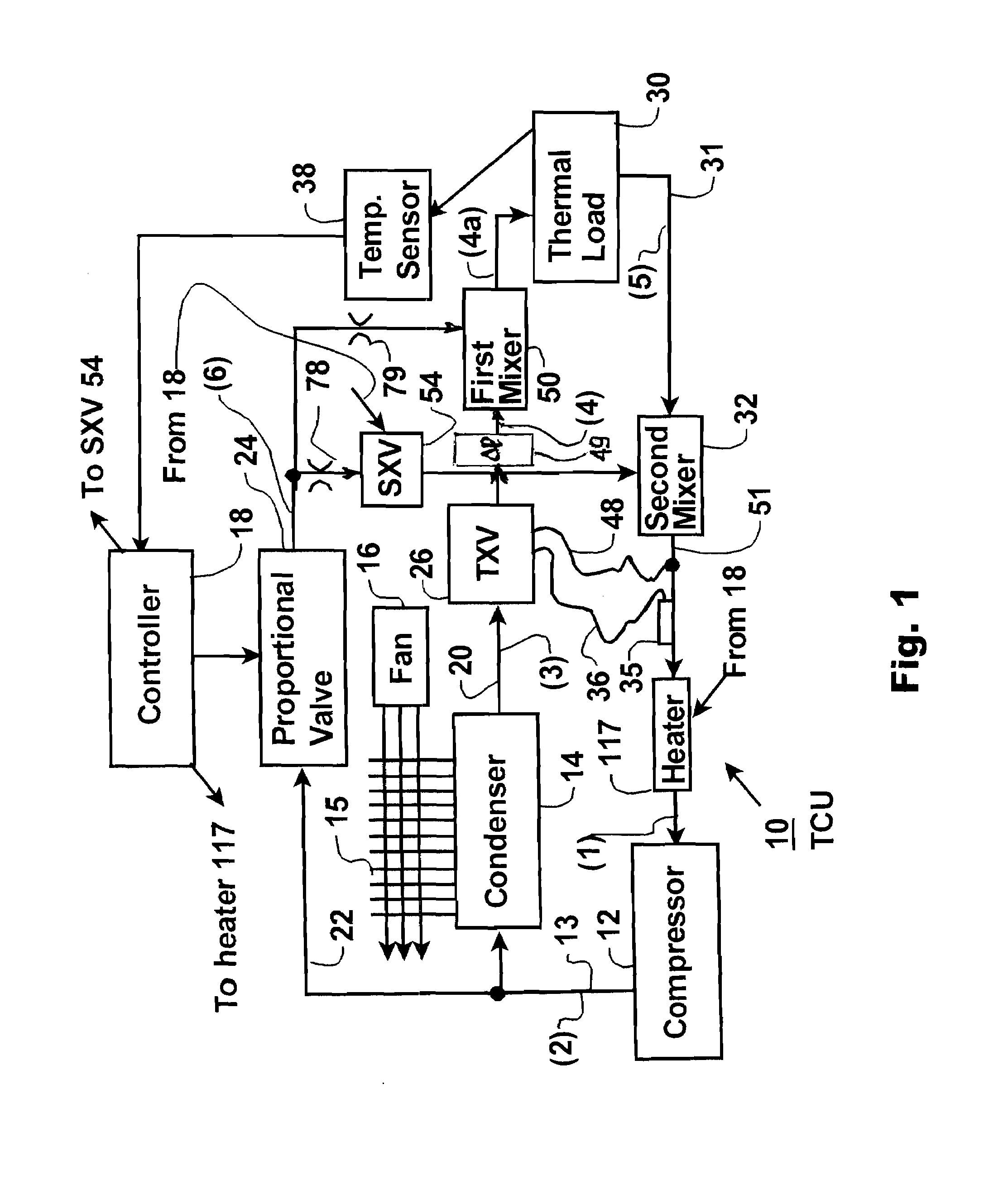
[0023]A generalized system utilizing post load mixing (PLM) is shown in FIG. 1, to which reference is now made. The thermal control system 10 or “TCU” is consistent with the TDSF concept but differentiated by incorporating the PLM approach, and forms a closed loop that encompasses an active thermal control system (TCU) 10 and a thermal load 30. The thermal load 30 is typically a heat exchanger that functions with a processing unit (not shown), such as a chuck for processing semiconductors. In the thermal control system 10 a refrigerant comprising a medium such as R-507 is input to a compressor 12 in gaseous form and a pressurized output is provided therefrom into a main line 13. One branch from the main line 13 includes an air cooled (in this example) condenser 14 having an external air-cooled fin structure 15 engaged by flow from a fan 16 shown only symbolically. The condenser 14 provides a fully or substantially liquefied output of refrigerant at an essentially ambient temperature...


PUM

PropertyMeasurementUnit
Volumeaaaaaaaaaa
Temperatureaaaaaaaaaa
Pressureaaaaaaaaaa

Abstract

In a temperature control system using a controlled mix of high temperature pressurized gas and a cooled vapor/liquid flow of the same medium to cool a thermal load to a target temperature in a high energy environment, particular advantages are obtained in precision and efficiency by passing at least a substantial percentage of the cooled vapor/liquid flow through the thermal load directly, and thereafter mixing the output with a portion of the pressurized gas flow. This “post load mixing” approach increases the thermal transfer coefficient, improves control and facilities target temperature change. Ad added mixing between the cooled expanded flow and a lesser flow of pressurized gas also is used prior to the input to the thermal load. A further feature, termed a remote “Line Box”, enables transport of the separate flows of the two phase medium through a substantial spacing from pressurizing and condensing units without undesired liquefaction in the transport lines.

Description

REFERENCES TO PRIOR APPLICATIONS[0001]This application relies for priority on similarly titled applications of the same inventors, namely a first provisional application filed Sep. 23, 2008, Ser. No. 61 / 192,881 and a second provisional application filed May 20, 2009, Ser. No. 61 / 179,745.BACKGROUND OF THE INVENTION[0002]With the growth of modern technology, improved temperature control systems have also been sought for maintaining a thermal load at a precise temperature under energy intensive conditions. Many such control systems also are required to change the temperature of the thermal load in accordance with process conditions, sometimes with great rapidity. As one illustration, semiconductor manufacturing equipment and processes are often dependent upon temperature control of the wafers or other elements on which various surfaces are being deposited or etched, using techniques which are highly energy intensive. It is thus often necessary to maintain a large semiconductor wafer wh...

Claims


Application Information

Patent Timeline
IPC IPC(8): G05D11/16F25B41/04G05D23/00F25B41/00F25B1/00
CPCF25B41/00F25B49/00F25B2600/2501F25B2400/01F25B49/02
Inventor COWANS, KENNETH W.COWANS, WILLIAM W.ZUBILLAGA, GLENN
Owner ADVANCED THERMAL SCI
Why Eureka
Try Eureka