Susceptor support shaft with uniformity tuning lenses for EPI process

a technology of uniform tuning and susceptor, applied in the field of susceptor, can solve the problems of affecting the accuracy of temperature measurement by the pyrometer, interfering with pyrometer readings, and periods of inaccurate temperature measurement, so as to reduce the variation of temperature measurement, reduce the effect of thermal mass, and fast ramp up and ramp down rate of the susceptor

Active Publication Date: 2016-12-27
APPLIED MATERIALS INC
View PDF30 Cites 4 Cited by
  • Summary
  • Abstract
  • Description
  • Claims
  • Application Information

AI Technical Summary

Benefits of technology

[0009]Embodiments of the invention generally relate to susceptor support shafts and process chambers containing the same. A susceptor support shaft supports a susceptor thereon, which in turn, supports a substrate during processing. The susceptor support shaft reduces variations in temperature measurement of the susceptor and / or substrate by providing a consistent path for a pyrometer focal beam directed towards the susceptor and / or substrate, even when the susceptor support shaft is rotated. The susceptor support shafts also have a relatively low thermal mass which enables fast ramp up and ramp down rates of a susceptor in the process chamber.

Problems solved by technology

As the susceptor support shaft is rotated during processing, the arms extending from the susceptor support shaft interrupt a pyrometer beam used to measure a temperature of the susceptor or the substrate, thus causing the interference of pyrometer readings.
This amount of light absorbed and scattered by the arms affects the amount of light transmitted by the pyrometer beam to the susceptor, and thus, affects the accuracy of the temperature measurement by the pyrometer.
Thus, the amount of light from the pyrometer beam reaching the susceptor varies as the susceptor support rotates, resulting in periods of inaccurate temperature measurement.

Method used


Image

  • Susceptor support shaft with uniformity tuning lenses for EPI process
  • Susceptor support shaft with uniformity tuning lenses for EPI process
  • Susceptor support shaft with uniformity tuning lenses for EPI process

Examples


Embodiment Construction

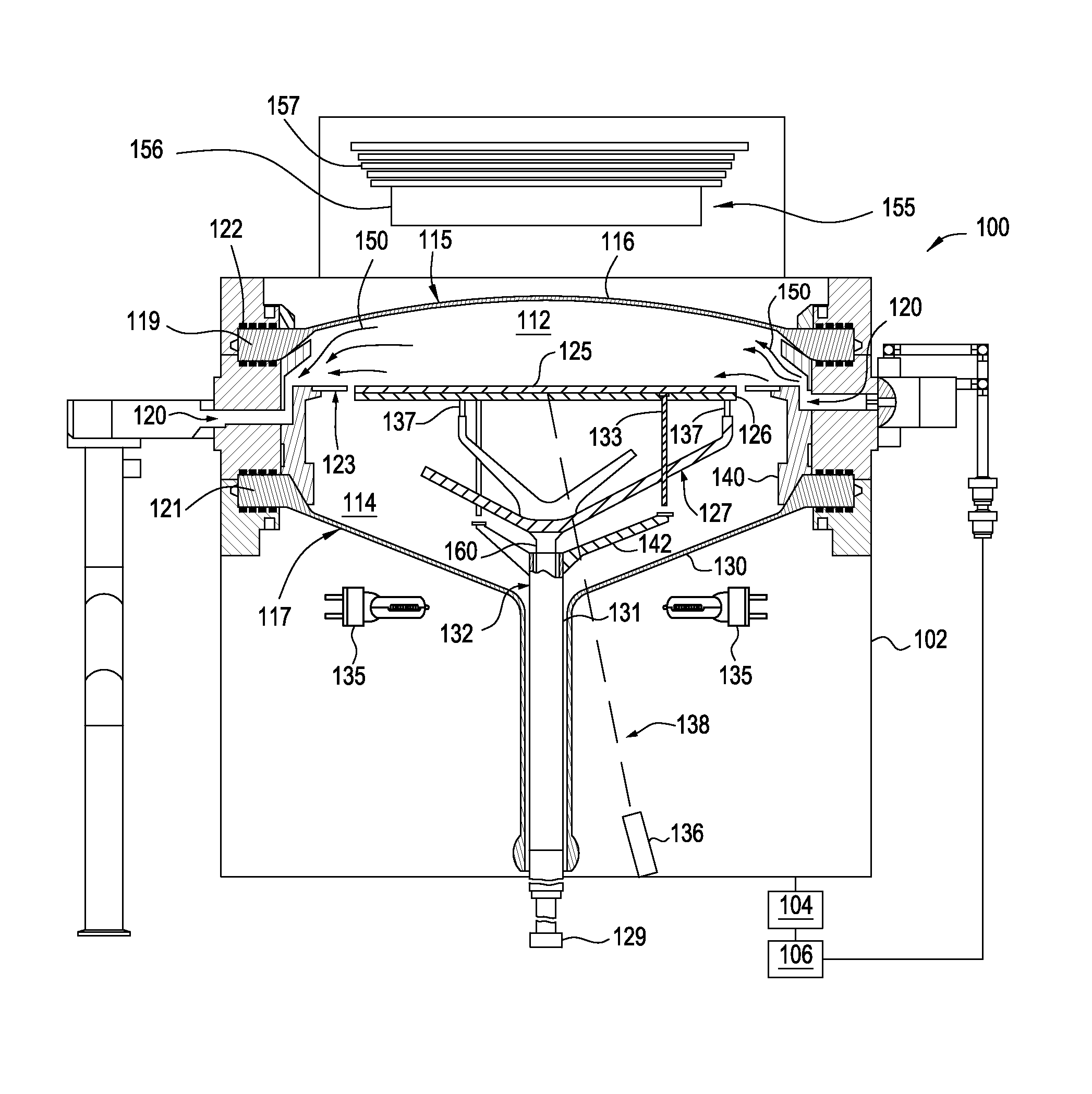
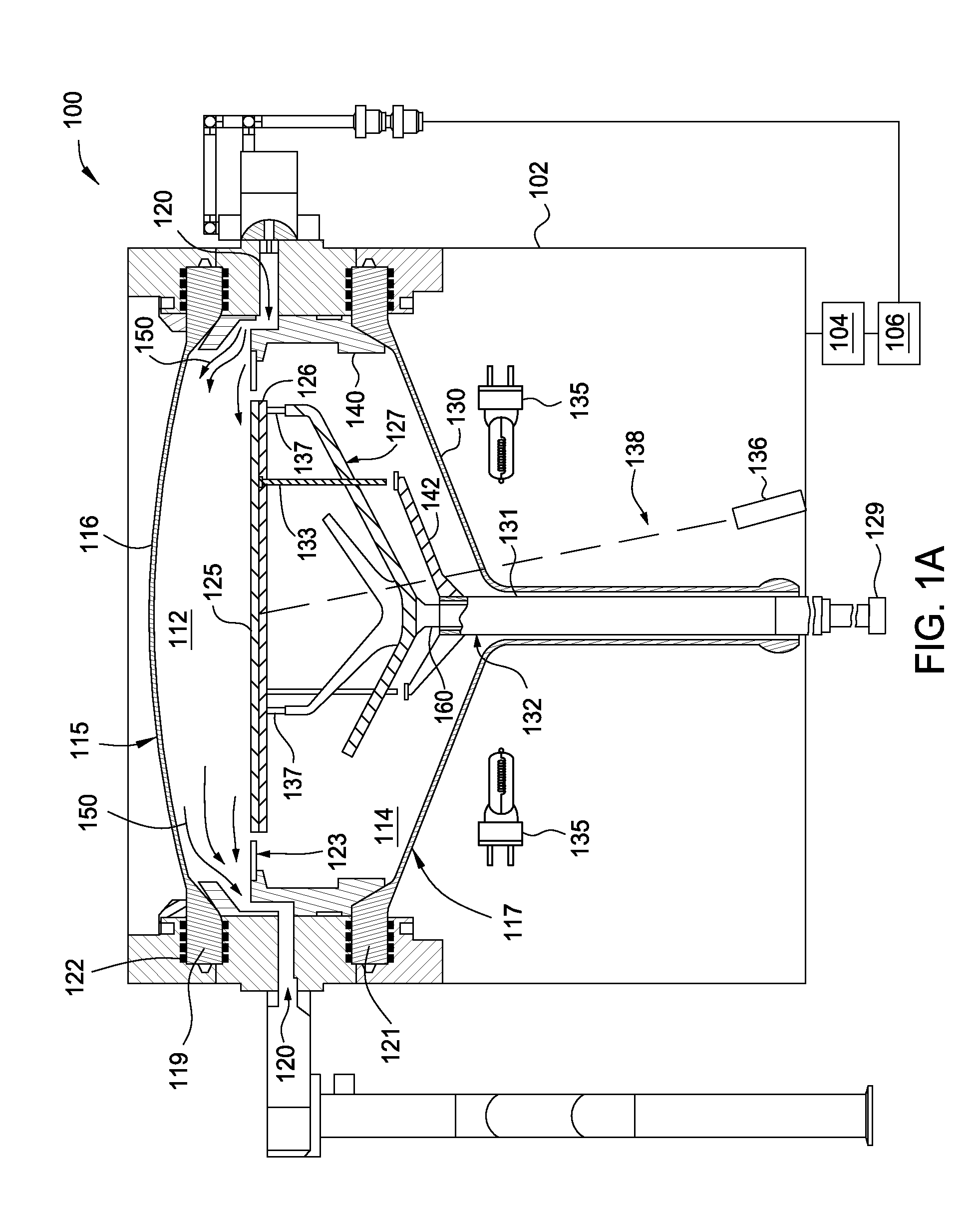
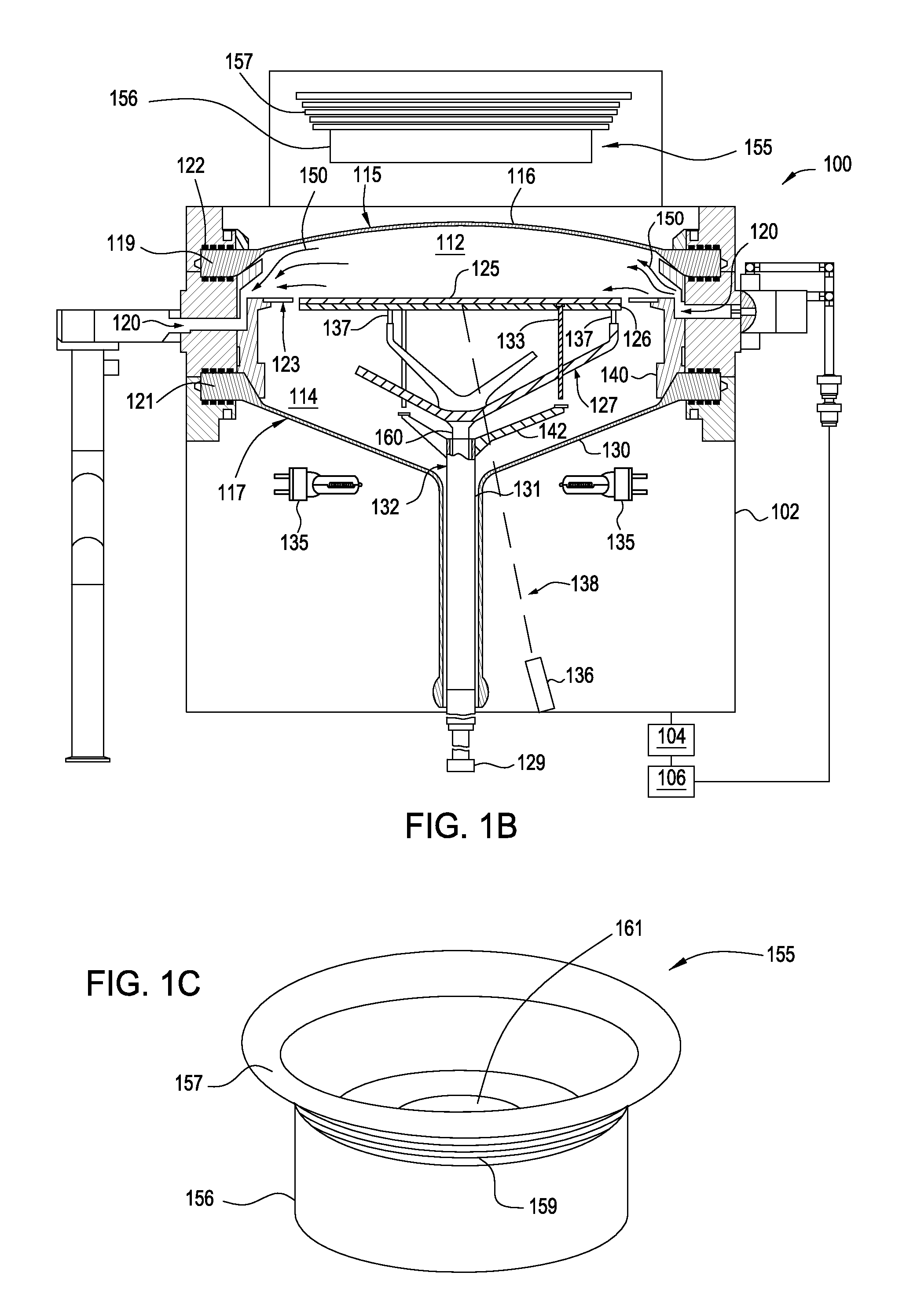
[0022]Embodiments of the invention generally relate to susceptor support shafts and process chambers containing the same. A susceptor support shaft supports a susceptor thereon, which in turn, supports a substrate during processing. The susceptor support shaft is designed to reduce variations in temperature measurement of the susceptor and / or substrate by providing the susceptor support shaft with a solid disc near the rotation center covering the pyrometer sensing path directed towards the susceptor and / or substrate. As the solid disc covers the pyrometer temperature reading path, the pyrometer reading show less interference, even when the susceptor support shaft is rotated. The solid disc covers only the pyrometer focal beam near the rotation center, so the susceptor support shaft has a relatively low thermal mass, which enables fast ramp up and ramp down rates of a process chamber. In some embodiments, a custom made refractive element can be removably placed on the top of the sol...


PUM

PropertyMeasurementUnit
temperatureaaaaaaaaaa

Abstract

Embodiments of the invention generally relate to susceptor support shafts and process chambers containing the same. A susceptor support shaft supports a susceptor thereon, which in turn, supports a substrate during processing. The susceptor support shaft reduces variations in temperature measurement of the susceptor and / or substrate by providing a consistent path for a pyrometer focal beam directed towards the susceptor and / or substrate, even when the susceptor support shaft is rotated. The susceptor support shafts also have a relatively low thermal mass which increases the ramp up and ramp down rates of a process chamber. In some embodiments, a custom made refractive element can be removably placed on the top of the solid disc to redistribute secondary heat distributions across the susceptor and / or substrate for optimum thickness uniformity of epitaxy process.

Description

CROSS-REFERENCE TO RELATED APPLICATIONS[0001]This application claims benefit of U.S. provisional patent application Ser. No. 61 / 798,503, filed Mar. 15, 2013 which is herein incorporated by reference.BACKGROUND[0002]Field[0003]Embodiments of the present invention generally relate to supporting substrates in processing chambers.[0004]Description of the Related Art[0005]During processing, substrates are positioned on a susceptor within a process chamber. The susceptor is supported by a susceptor support shaft, which is rotatable about a central axis. The susceptor support shaft includes multiple arms extending therefrom—usually three to six—which support the susceptor. As the susceptor support shaft is rotated during processing, the arms extending from the susceptor support shaft interrupt a pyrometer beam used to measure a temperature of the susceptor or the substrate, thus causing the interference of pyrometer readings. Even though the arms may be formed from quartz, which is general...

Claims


Application Information

Patent Timeline
Patent Type & Authority Patents(United States)
IPC IPC(8): F27D5/00H01L21/302H05B1/02C23C14/00
CPCH05B1/0227H05B2203/032
Inventor CONG, ZHEPENGRAMACHANDRAN, BALASUBRAMANIANISHII, MASATOLI, XUEBINSAMIR, MEHMET TUGRULLAU, SHU-KWANBRILLHART, PAUL
Owner APPLIED MATERIALS INC
Why Eureka
Try Eureka