Vitreous silica crucible and method of manufacturing the same

a technology of vitreous silica and crucible, which is applied in the direction of manufacturing tools, crystal growth process, polycrystalline material growth, etc., can solve the problems of inability to employ the jp-u-2533643 technique, burdensome laser marker movement, and mixing of crucibles having different specifications, so as to prevent mixing of crucibles during manufacturing process.

Active Publication Date: 2017-01-03
SUMCO CORP
View PDF13 Cites 0 Cited by
  • Summary
  • Abstract
  • Description
  • Claims
  • Application Information

AI Technical Summary

Benefits of technology

[0012]Thus, any of the prior art is not useful for identification of various kinds of crucibles having different specifications, and thus the operators make a lot of effort to prevent mix-up of the crucibles in the manufacturing process.
[0013]The present invention has been made in view of these circumstances, and provides a method of manufacturing a vitreous silica crucible so that mix-up of crucibles in the manufacturing process can be prevented.
[0015]The present inventors have made extensive research on how to prevent mix-up of crucibles in the manufacturing process, and come up with an idea of marking an identifier after the taking-out process and before the honing process.
[0018]Furthermore, the present inventors have come up with an idea of marking an identifier comprised of one or more groove line. The “identifier” refers to a symbol which can be used for identification of the kind of a crucible, and is comprised of, for example, character, numeric character, or bar code. The present invention use an identifier comprised of one or more groove line, and thus can produce various kinds of identifiers, and thus can recognize various kinds of crucibles easily.
[0020]Thus, according to the present invention, the mix-up of crucibles during manufacturing process can be prevented.

Problems solved by technology

In particular, when the difference of the specifications is not discernable from the appearance, there is a problem that mix-up of the crucibles having different specifications can occur.
Therefore, in view of manufacturing efficiency, it is not feasible to employ the technique of JP-U-2533643 in order to identify crucibles having various specifications.
Furthermore, in order to irradiate the portion with a YAG laser through the vitreous silica member, it is necessary to radiate the YAG laser from the inside to the outside of the crucible, and it is burdensome to move the laser marker into the inside of the crucible for each marking.
Therefore, it is extremely difficult to utilize the technique of JP-A-H11-209136 for marking of a crucible.

Method used


Image

  • Vitreous silica crucible and method of manufacturing the same
  • Vitreous silica crucible and method of manufacturing the same
  • Vitreous silica crucible and method of manufacturing the same

Examples


example

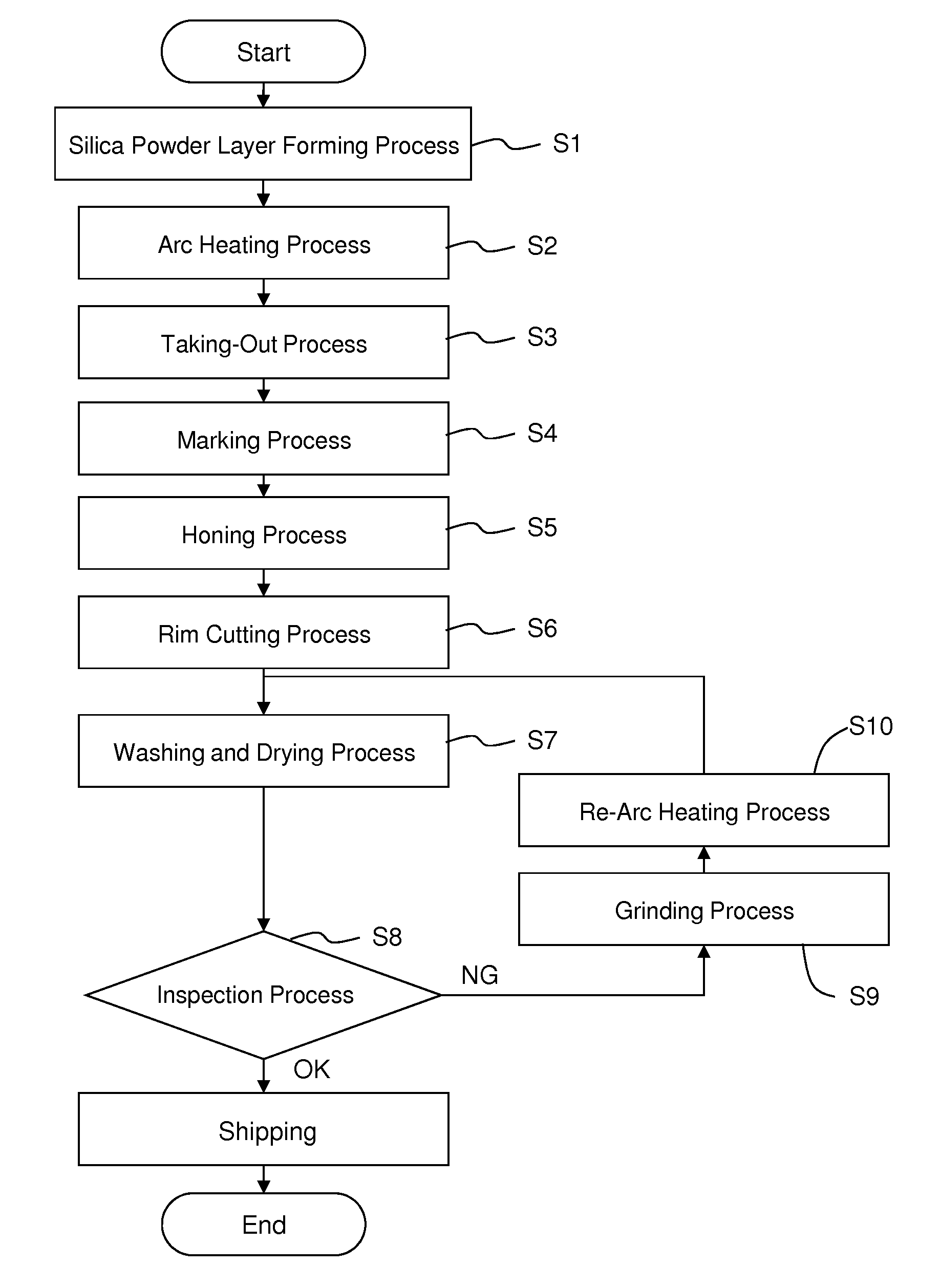
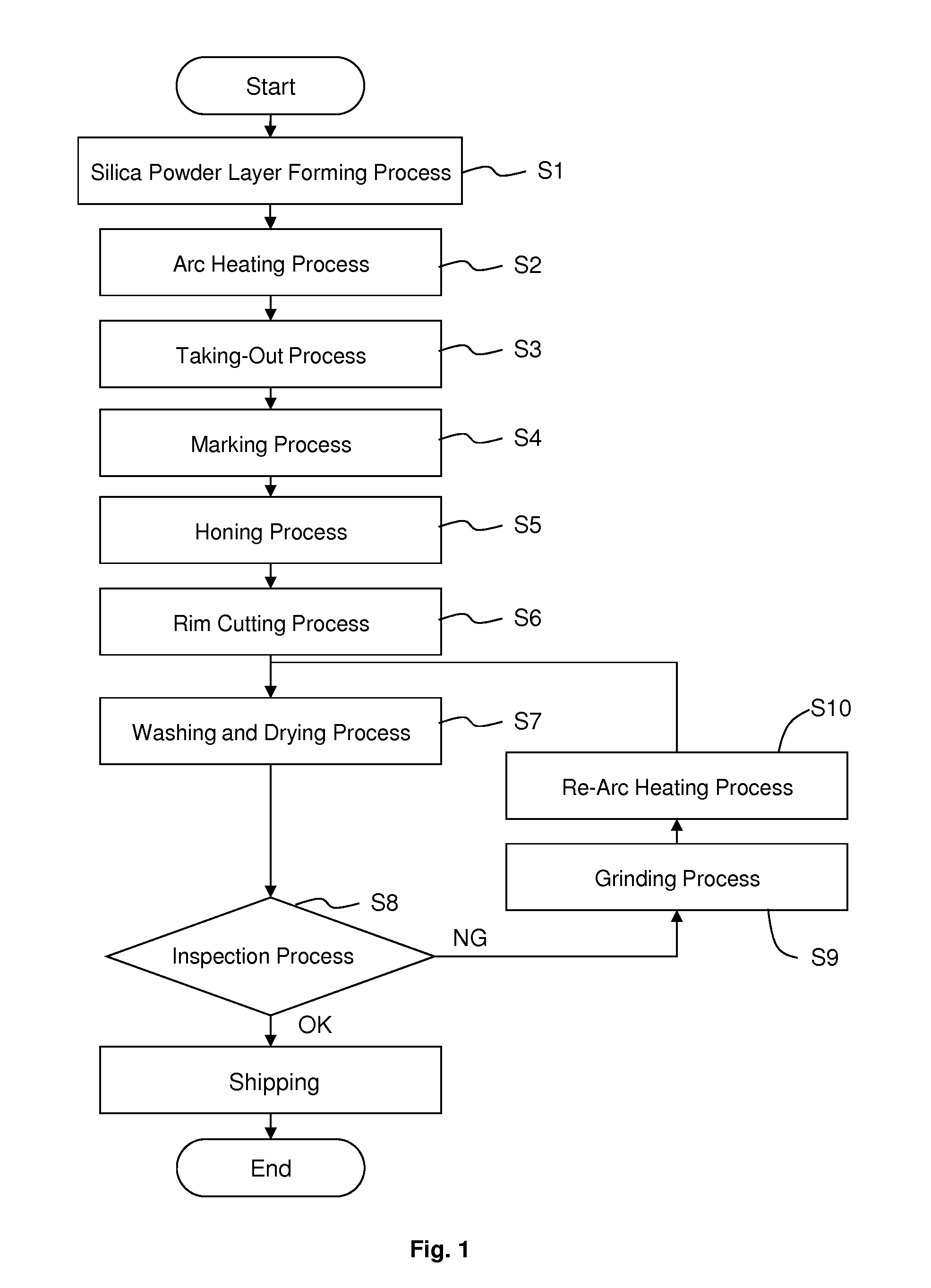
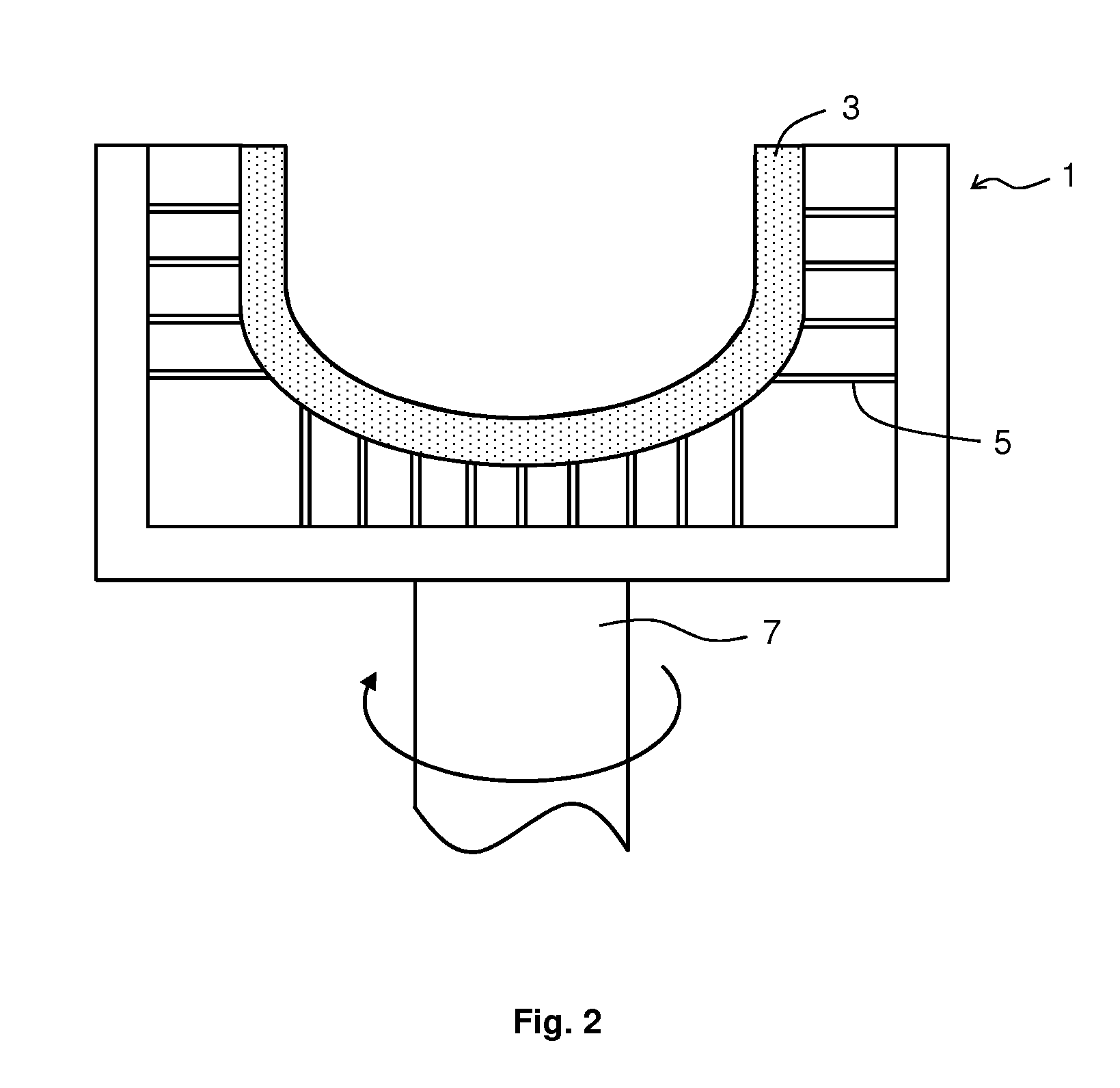
[0067]Silica powder was deposited, in a thickness of 15 mm, on an inner surface of a mold having an opening diameter of 610 mm, to form a silica powder layer. Then the silica powder layer was fused by arc heating while depressurizing the silica powder layer from the mold side, to form a vitreous silica crucible having, from the inner side, a transparent layer and a bubble-containing layer. Next, the vitreous silica crucible was taken out of the mold. Then, the identifier “ABC” was marked on the crucible having unfused silica powder attached thereto in the conditions shown in Table 1 by use of a carbon dioxide laser having a maximum output of 30 W. The value in % of the laser output is with respect to the maximum output.

[0068]Then, the unfused silica powder layer was removed by spraying high-pressure water to the outer surface of the vitreous silica crucible in the honing process. After this process, the identifier was observed to see if the identifier was visibly recognizable. The c...


PUM

PropertyMeasurementUnit
widthaaaaaaaaaa
depthaaaaaaaaaa
widthaaaaaaaaaa

Abstract

The present invention provides a method of manufacturing a vitreous silica crucible including: a taking-out process of taking out the vitreous silica crucible from the mold, a honing process of removing the unfused silica powder layer on the outer surface of the vitreous silica crucible, and further comprising, after the taking-out process and before the honing process, a marking process of marking an identifier comprised of one or more groove line on the outer surface of the vitreous silica crucible, wherein the groove line after the honing process has a depth of 0.2 to 0.5 mm, and a width of 0.8 mm or more at the opening of the groove line.

Description

CROSS-REFERENCE TO RELATED APPLICATION[0001]This application is related to Japanese Patent Application No. 2010-294593 filed on Dec. 29, 2010, whose priority is claimed and the disclosure of which is incorporated by reference in its entirety.BACKGROUND OF THE INVENTION[0002]1. Field of the Invention[0003]The present invention relates to a vitreous silica crucible and a method of manufacturing the same.[0004]2. Description of the Related Art[0005]In general, silicon single crystal is manufactured by melting high-purity polycrystalline silicon in a vitreous silica crucible to obtain silicon melt, dipping an end of a seed crystal to the silicon melt, and pulling the seed crystal while rotating it.[0006]In general, in a manufacturing process of a vitreous silica crucible, silica powder is deposited on an inner surface of a rotating mold, and arc fusing process is carried out to fuse the silica powder. Thereafter, a honing process is carried out to remove unfused silica powder attached o...

Claims


Application Information

Patent Timeline
Patent Type & Authority Patents(United States)
IPC IPC(8): C30B19/02C30B35/00C30B15/00
CPCC30B35/002C30B15/00Y10T117/10B41M5/262C03B20/00C30B15/10C30B29/06C03B19/095C03C23/0025
Inventor SUDO, TOSHIAKISATO, TAIRAIKEHATA, SHUICHISHONAI, MANABUNISHI, TAKUJISATOU, TAKAYAYAMAZAKI, SHINSUKE
Owner SUMCO CORP
Why Eureka
Try Eureka