System and method for tunnel air ventilation

a tunnel air and ventilation system technology, applied in the field of systems and methods, can solve the problems of pollution death, short term and long term effects on the health of drivers and passengers, and the sickness of pollution and even death of drivers, and achieve the effects of less expensive, convenient installation or implementation, and safer repair and maintenan

Active Publication Date: 2017-01-03
GHAVAMI AHMADREZA
View PDF15 Cites 7 Cited by
  • Summary
  • Abstract
  • Description
  • Claims
  • Application Information

AI Technical Summary

Benefits of technology

[0025]In one embodiment, we describe a method and system for Tunnel Air Ventilation, which is very practical, economical, and easy to install or implement. The repair and maintenance is safer and less expensive. The overall cost of installation and repair is lower. The system is more stable, and thus, safer for the vehicles and people. It is not damaged by sand, and it does not cause damage to vehicles by sand. So, the risk is minimized. The overall value for the government and society is very high. The efficiency and low down time translates to a cleaner air in the tunnel, which is a major health issue for people, which causes sickness and even death for pollution and toxicity, or by fatal accidents in the tunnel, due to intoxication of the drivers or dizziness. The short term and long term effects on the health of drivers and passengers are huge, especially children, who are very sensitive to the polluted air or toxins, or for people with asthma or allergy, which can be fatal. Thus, our system and method can solve all these problems, with so many advantages, for millions of people around the world, and for many years to come.

Problems solved by technology

The efficiency and low down time translates to a cleaner air in the tunnel, which is a major health issue for people, which causes sickness and even death for pollution and toxicity, or by fatal accidents in the tunnel, due to intoxication of the drivers or dizziness.
The short term and long term effects on the health of drivers and passengers are huge, especially children, who are very sensitive to the polluted air or toxins, or for people with asthma or allergy, which can be fatal.

Method used


Image

  • System and method for tunnel air ventilation
  • System and method for tunnel air ventilation
  • System and method for tunnel air ventilation

Examples


Embodiment Construction

[0042]The current and above mentioned flaws, cost, operational inefficiency, and archaic approach to the tunnel design have motivated the inventor here to come up with a new way to design an upcoming tunnel ventilation system.

[0043]As a result, we have a new way of approach to tunnel ventilation system that is more cost effective, with considerably fewer working parts, easier repairs, as opposed to difficulty in operation and changing parts, and heavy reliance on bad and old tunnel design.

[0044]Specification, differentiation, and the explanation of the new method:

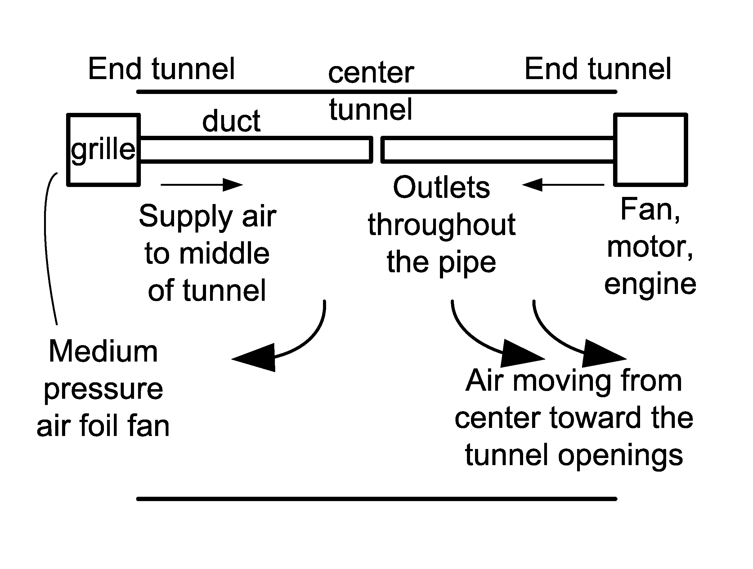
[0045]The system and method is fundamentally based upon continuous “Partial Positive Pressure” (P.P.P.), which applies to the total volume of the tunnel. In the interest to clarify the suggested subject matter, we conducted a simple experiment that can prove the functionality of the new method.

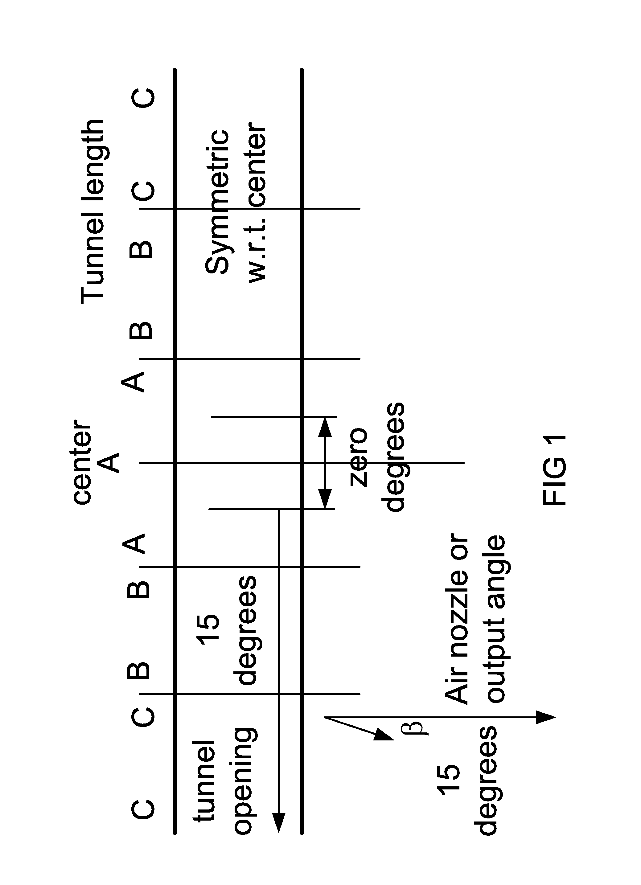
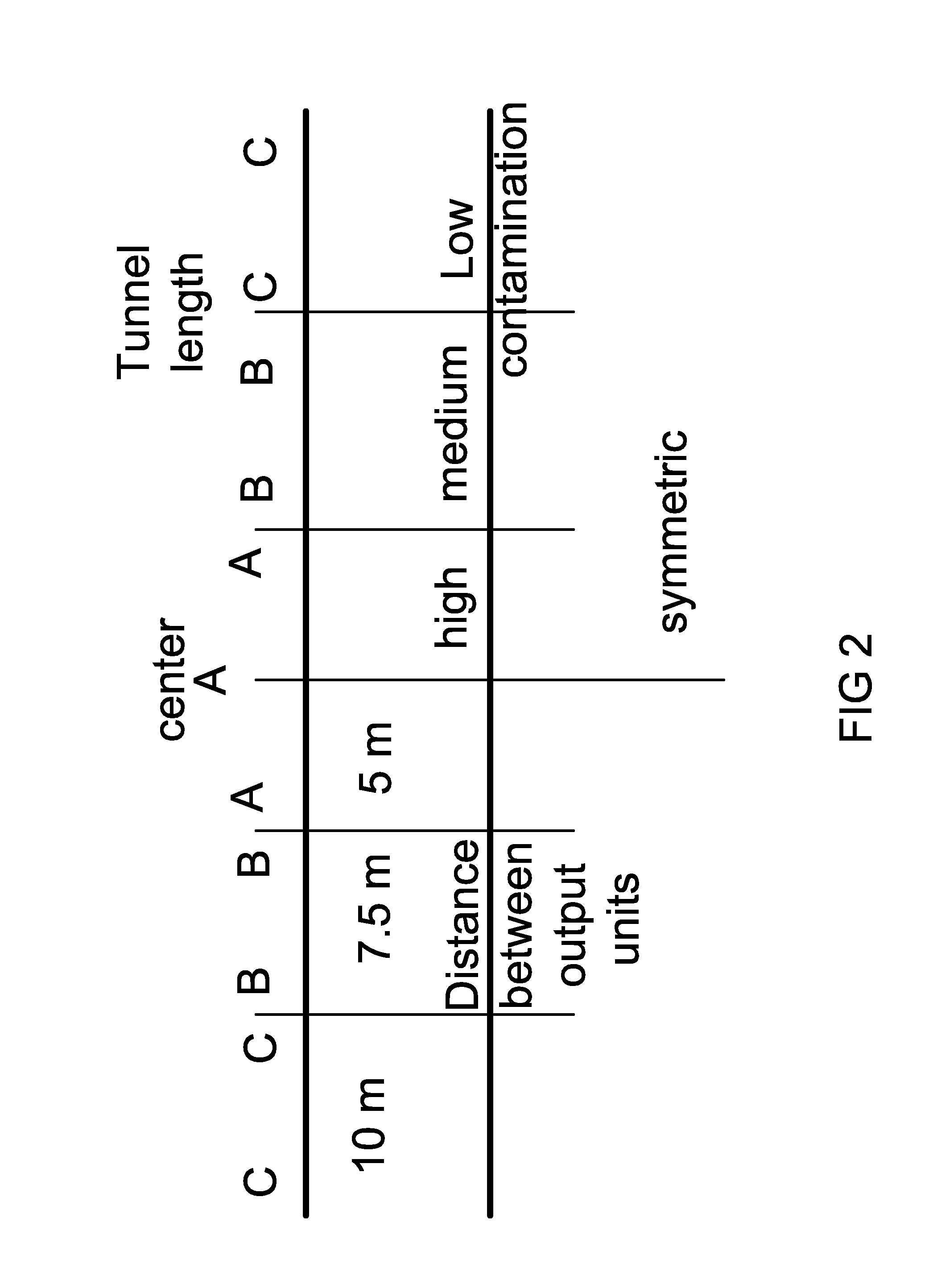
[0046]The Experiment, to show the physics of our method and system:

[0047]We have done both experiment and simulation on this model: ...


PUM


Abstract

In one example, we describe a method and system for Tunnel Air Ventilation, which is very practical, economical, and easy to install or implement. The repair and maintenance is safer and less expensive. The overall cost of installation and repair is lower. The system is more stable, and thus, safer for the vehicles and people. It is not damaged by sand, and it does not cause damage to vehicles by sand. So, the risk is minimized. The overall value for the government and society is very high. The efficiency and low down time translates to a cleaner air in the tunnel, which is a major health issue for people, which causes sickness and even death for pollution and toxicity, or by fatal accidents in the tunnel, due to intoxication of the drivers or dizziness. Different variations are also discussed and shown.

Description

BACKGROUND OF THE INVENTION[0001]For the past few decades, the important subject of the tunnel air ventilation (for elimination or minimizing the internal pollutions) has been mostly done by similar conventional methods. That is, the current standards of operation have remained the same and intact. This made the illusion that there were no other ways to solve this problem. The basis of the named method is (and has been) using the ceiling type jet fans, using precise calculations, for capacities and power, which are calculated and selected in accordance to numerous different factors.[0002]The designer, who makes the various calculations and designs, should pay close attention to many different factors, some of which are (the most important ones):[0003]1—Physical aspect of tunnel (length, section, type, directions, mechanical specifications, and the like).[0004]2—Direction and velocity of the wind pressure, speed and direction of the changing wind patterns, and total force of wind ene...

Claims


Application Information

Patent Timeline
Patent Type & Authority Patents(United States)
IPC IPC(8): E21F1/00
CPCE21F1/003
Inventor GHAVAMI, AHMADREZA
Owner GHAVAMI AHMADREZA
Why Eureka
Try Eureka