

Imaging lens
a technology of imaging lenses and chromatic aberration, applied in the field of imaging lenses, can solve the problems of disadvantageous technique, reduced cost, and rare application of light and compact fixed-focus cameras, and achieve the effect of reducing thickness and effective correction of chromatic aberration
- Summary
- Abstract
- Description
- Claims
- Application Information
AI Technical Summary
Benefits of technology
Problems solved by technology
Method used
Image

Examples
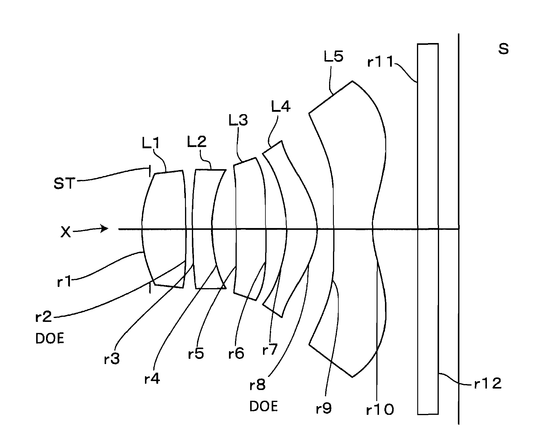
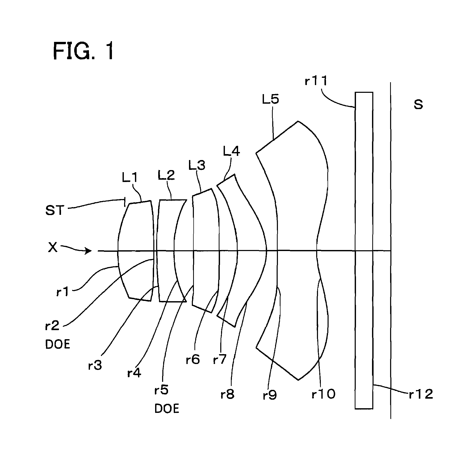
first embodiment
[0065
[0066]Table 1 shows basic lens data. In this embodiment, diffractive optical surfaces DOE are formed on the image side surface r2 of the first lens L1 and the object side surface r5 of the third lens L3.
[0067]
TABLE 1Surface dataSurface No.rdnvObject surface∞∞ 1 (stop)1.67000.61581.538656.1 2 (DOE)−16.74160.0506 36.19990.2901.624225.4 41.96170.3392 5 (DOE)13.95840.4411.538656.1 6−24.98810.307 7−1.68960.50041.538656.1 8−0.91110.1851 919.53130.67131.538656.1101.20490.659011∞0.301.520164.012∞0.30Image plane∞f = 3.8284,Fno = 2.5186,ω = 36.6°
[0068]Next, data on aspheric surface coefficients and coefficients of optical path difference function of the diffractive optical surfaces in the first embodiment are listed below.
[0069]
TABLE 2Aspheric dataFirst surfaceSecond surfaceAspheric coefficientAspheric coefficientk = −2.1898E+00k = 16.1942E+00A2 = 0.0000E+00A2 = 0.0000E+00A4 = 4.7661E−02A4 = −1.0516E−01A6 = −1.678E−02A6 = 4.8217E−01A8 = 1.4794E−02A8 = −1.2854E+00A10 = −1.1732E−01A10 = 1....
second embodiment
[0072
[0073]Basic lens data is shown below in Table 3. In the second embodiment, diffractive optical surfaces DOE are formed on the image side surface r2 of the first lens L1 and the image side surface r6 of the third lens L3.
[0074]
TABLE 3Surface dataSurface No.rdnvObject surface∞∞ 1 (stop)1.74350.62721.538656.1 2 (DOE)−25.01340.1223 36.19990.291.624625.4 42.12710.3442 513.51210.4411.538656.1 6 (DOE)−24.98810.307 7−1.71170.45251.538656.1 8−0.91920.2342 915.30850.58181.538656.1101.16430.658911∞0.3001.520164.012∞0.300Image plane∞f = 3.9118, Fno = 2.5075, ω = 36.0°
[0075]Next, data on aspheric surface coefficients and coefficients of optical path difference function of the diffractive optical surfaces in the second embodiment are listed in Table 4
[0076]
TABLE 4Aspheric dataFirst surfaceSecond surfaceAspheric coefficientAspheric coefficientk = −2.5162E+00k = 30.2537E+00A2 = 0.0000E+00A2 = 0.0000E+00A4 = 4.0207E−02A4 = −1.1497E−01A6 = −2.1024E−02A6 = 3.8048E−01A8 = −2.5527E−02A8 = −1.2234E+...
third embodiment
[0079
[0080]Basic lens data is shown below in Table 5. In the third embodiment, diffractive optical surfaces DOE are formed on the image side surface r2 of the first lens L1 and the object side surface r7 of the fourth lens L4.
[0081]
TABLE 5Surface dataSurface No.rdnvObject surface∞∞ 1 (stop)1.71490.65161.538656.1 2 (DOE)−25.01340.1032 36.19990.291.624625.4 42.10580.3513 515.04460.44101.538656.1 6−24.98810.307 7 (DOE)−1.71380.44781.538656.1 8−0.91750.2577 915.28430.55071.538656.1101.14800.658911∞0.3001.520164.012∞0.300Image plane∞f = 3.9354, Fno = 2.5066, ω = 35.9°
[0082]Next, data on aspheric surface coefficients and coefficients of optical path difference function of the diffractive optical surfaces in the third embodiment are listed in Table 6.
[0083]
TABLE 6Aspheric dataFirst surfaceSecond surfaceAspheric coefficientAspheric coefficientk = −2.3271E+00k = −99.0E+00A2 = 0.0000E+00A2 = 0.0000E+00A4 = 4.3840E−02A4 = −1.0147E−01A6 = −2.1049E−02A6 = 4.1108E−01A8 = 6.341E−04A8 = −1.3381E+00...
PUM
 Abstract
Description
Claims
Application Information