
Connector

a technology of connecting wires and rubber plugs, applied in the direction of couplings/cases, coupling device connections, electrical equipment, etc., can solve the problems of reducing sealing performance, reducing and unable to use many types of wires, etc., to achieve the effect of expanding the range of applicable wires

Active Publication Date: 2017-01-17
SUMITOMO WIRING SYST LTD
View PDF8 Cites 2 Cited by
  • Summary
  • Abstract
  • Description
  • Claims
  • Application Information

AI Technical Summary

Benefits of technology

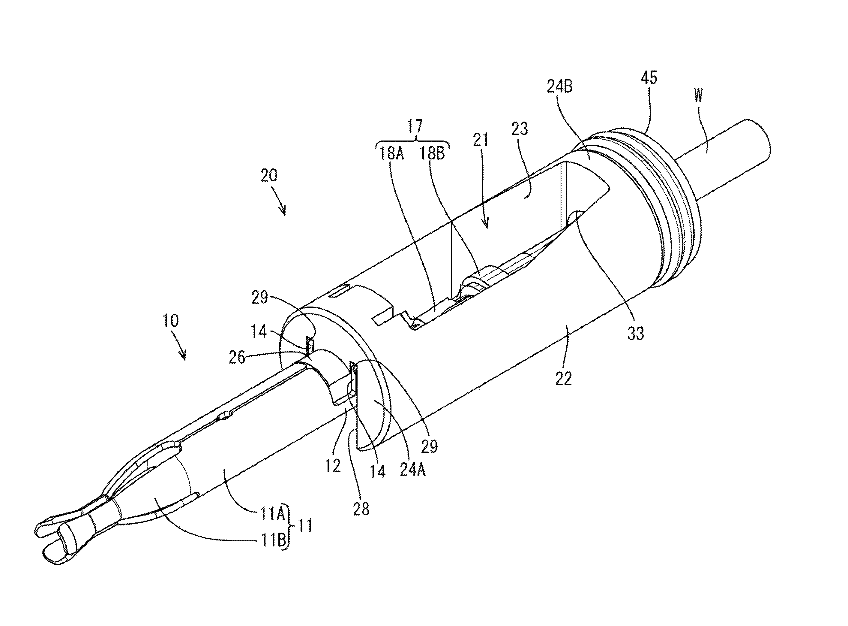
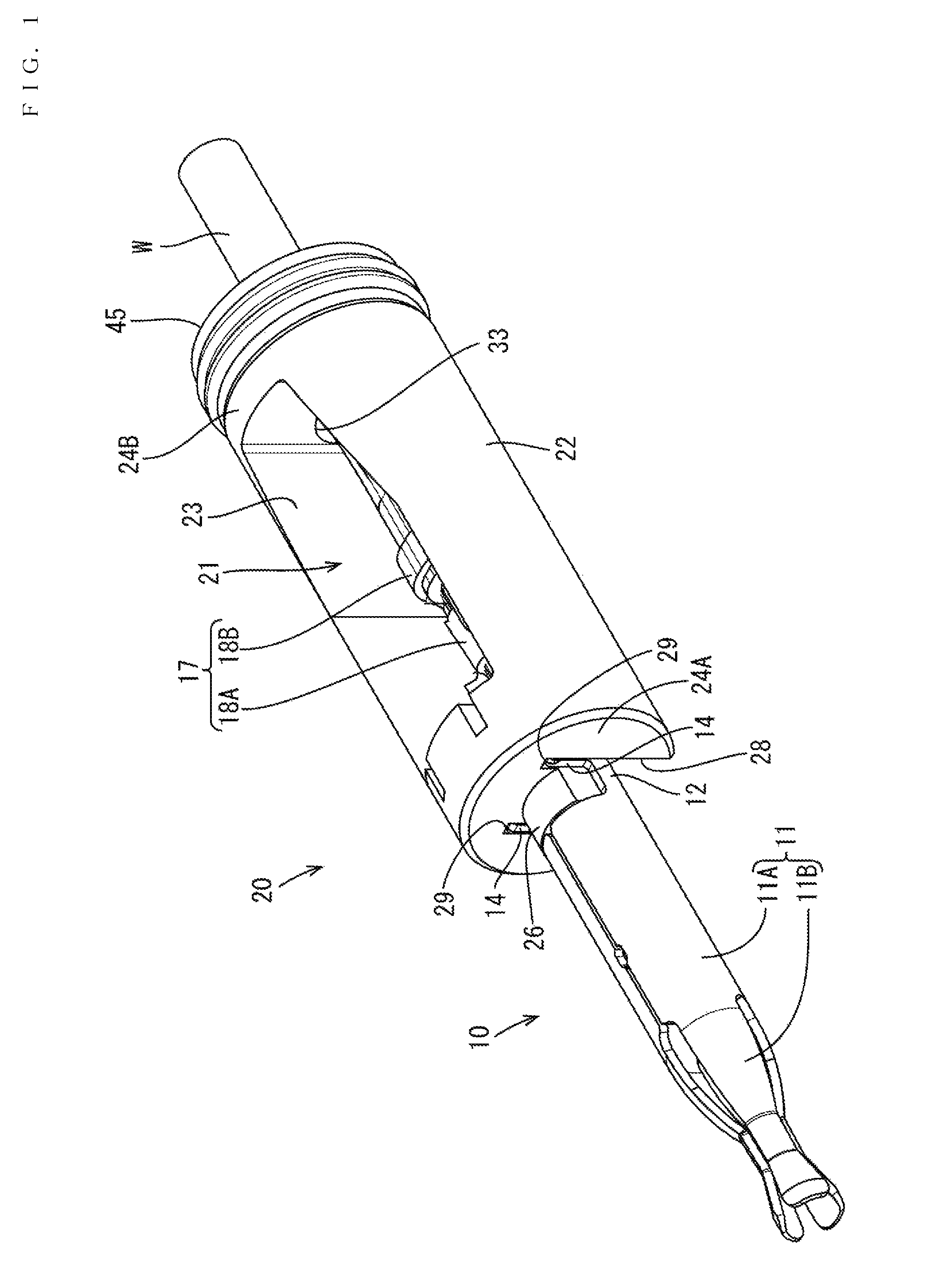
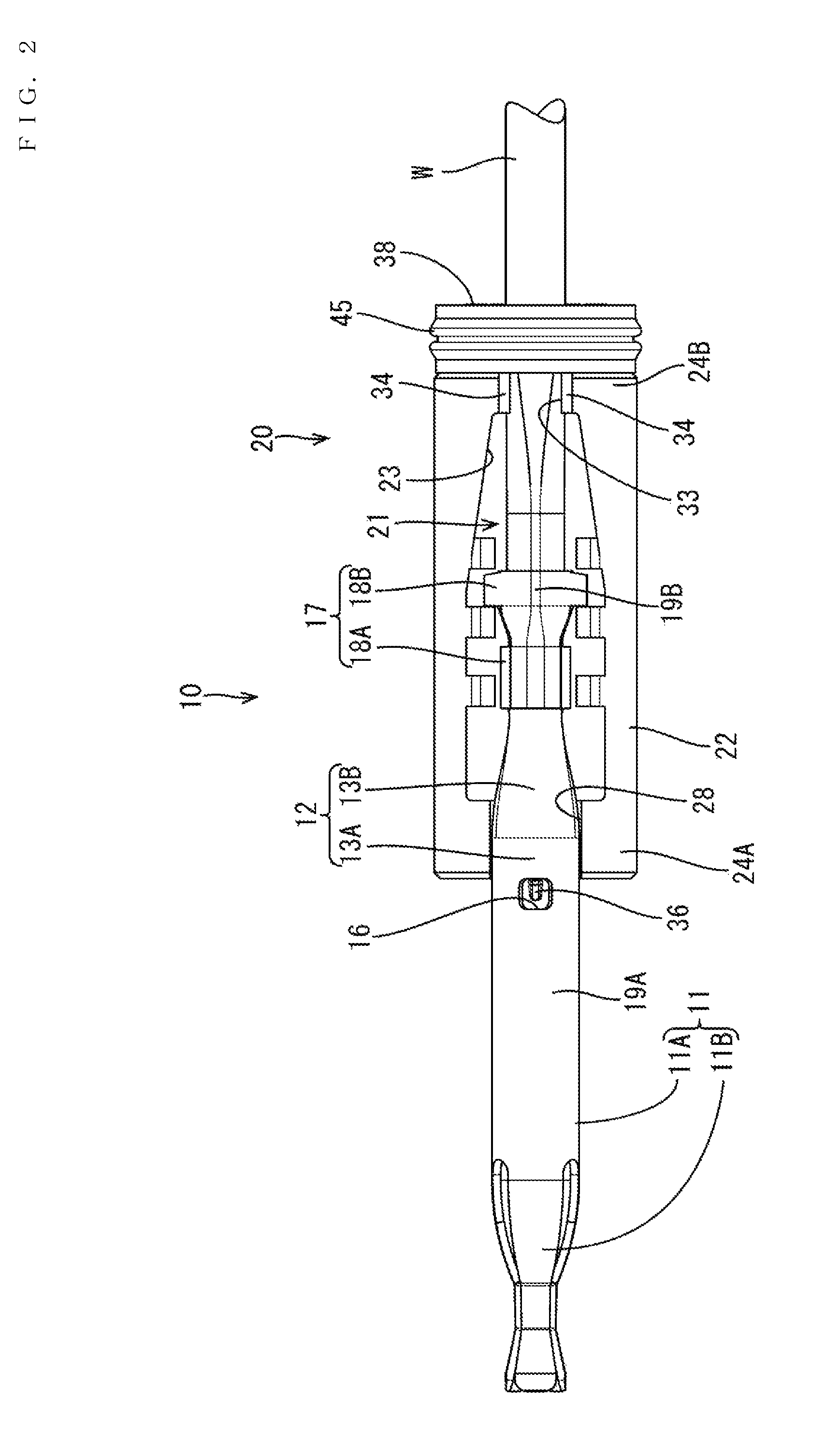
[0008]According to this configuration, the center position of the wire is displaced more toward the bottom plate from the center position of the terminal connecting portion by crimping the barrels to the wire particularly in the case of a thin wire than in the case of a thick wire. However, the center position of the wire sealing hole is displaced toward the bottom plate from the center position of the terminal connecting portion so that the wire can be pulled directly out backward. Thus, the amount of squeezing of an inner peripheral sealing surface of the wire sealing hole can be made substantially equal over the entire circumference and a reduction of sealing performance is avoided.
[0009]On the other hand, in the case of a thick wire, the center position of the wire is displaced toward a side opposite to the bottom plate from the center position of the wire sealing hole by crimping the pair of barrels to the wire. However, the amount of squeezing of the inner peripheral sealing surface of the wire sealing hole is originally larger than in the case of a thin wire and the inner peripheral sealing surface of the wire sealing hole can be held in close contact with the outer peripheral surface of the wire over the entire circumference. Thus, sealing performance is not reduced. Accordingly, sealing performance can be ensured for both thin wires and thick wires and a range of applicable wires can be expanded.
[0012]According to the technology disclosed by this specification, it is possible to ensure sealing performance for both thin wires and thick wires and expand a range of applicable wires.

Problems solved by technology

The above-described electrical contact portion is of a type called a closed barrel and diameters of usable wires are limited sufficiently so that many types of wires cannot be used.
Further, the amount of compressing of a thin wire against an inner peripheral sealing surface of a rubber plug mounted behind a terminal fitting is originally small.
Thus, if a center position of the wire is displaced down from a center position of the rubber plug, the amount of squeezing becomes smaller on an upper part of the inner peripheral sealing surface of the rubber plug, thereby reducing sealing performance.

Method used


Image

  • Connector
  • Connector
  • Connector

Examples


Embodiment Construction

[0025]An embodiment of the invention is described on the basis of FIGS. 1 to 12. In this embodiment, a charging connector is mounted on the tip of a gun-shaped case (not shown) and is connected to a vehicle-side connector provided in a vehicle.

[0026]The charging connector C is a five-pole connector and includes terminal fittings 10 connected to ends of wires W and a housing 50 for accommodating the terminal fittings 10, as shown in FIG. 8.

[0027]The terminal fittings 10 include two power terminals, one ground terminal and two signal terminals and basic structures thereof are similar although diameters and the like may differ depending on the type. The following description of the signal terminal is given as an example.

[0028]The terminal fitting 10 is a female terminal and formed into a shape as shown in FIGS. 9 and 10 by press-forming a metal plate with excellent electrical conductivity.

[0029]The terminal fitting 10 has a terminal connecting portion 11, a coupling 12 and a wire conne...


PUM


Abstract

A connector (C) has a terminal fitting (10) including a terminal connecting portion (11) to be connected to a mating terminal and barrels to be crimped to a wire (W). A housing (50) has a terminal accommodating chamber (57) that is configured to accommodate the terminal fitting (10). A sleeve (20) has an accommodation space (21) configured to accommodate the barrels crimped to the wire (W). A rubber plug (45) includes a center hole (46) and is configured so that the wire (W) extending back from a rear wall (24B) of the accommodation space (21) penetrates therethrough in a sealed state. A rear holder (60) obstructs rearward movement of the terminal fitting (10) via the sleeve (20). A center position (P2) of the center hole (46) is displaced toward a rear bottom plate (19B) from a center position (P1) of the terminal connecting portion (11).

Description

BACKGROUND[0001]1. Field of the Invention[0002]The invention relates to a connector.[0003]2. Description of the Related Art[0004]Japanese Patent No. 5044508 discloses a connector for retaining a terminal fitting by a sleeve. This terminal fitting includes an electrical contact portion to be connected electrically to a terminal fitting of a mating connector, a hollow cylindrical wire connecting portion to be connected to a core of a wire and a flange on an end part of the wire connecting portion near the electrical contact portion. The sleeve contacts the flange from behind and a rear holder contacts the sleeve from behind. The terminal fitting is retained in a connector housing by fixing the rear holder to the connector housing.[0005]The above-described electrical contact portion is of a type called a closed barrel and diameters of usable wires are limited sufficiently so that many types of wires cannot be used. Open barrels can be used to accommodate wires ranging from thin wires t...

Claims


Application Information

Patent Timeline
Patent Type & Authority Patents(United States)
IPC IPC(8): H01R9/05H01R13/52H01R13/436
CPCH01R13/4367H01R13/5205H01R4/185
Inventor UCHIDA, MASASHI
Owner SUMITOMO WIRING SYST LTD
Learn More