Magnetic pulse welding in medical power manufacturing

a technology of magnetic pulse welding and medical power manufacturing, applied in the field of electrochemical cells, can solve the problems of increasing the difficulty of assembling and manufacturing such small intricate devices, difficult to join and bond these components together, and typical bonding techniques such as laser and resistance welding practices are not always ideal for joining components. , to achieve the effect of reducing manufacturing costs, increasing cell design capabilities, and reducing construction complexity

Inactive Publication Date: 2017-01-24
WILSON GREATBATCH LTD
View PDF15 Cites 9 Cited by
  • Summary
  • Abstract
  • Description
  • Claims
  • Application Information

AI Technical Summary

Benefits of technology

[0011]In this magnetic pulse welding method, two dissimilar materials, particularly of significantly dissimilar melting temperatures, are joined together in a strong bond. In that respect, the present invention comprises a method by which materials having dissimilar melting temperatures are directly joined by the application of an electro-magnetic force over a short duration of time. Magnetic pulse welding works by generating an electro-magnetic force that physically drives a first material into a second material such that they collide together. The impaction force generated during the collision of the two materials is of enough energy that the two materials become permanently joined together.
[0015]Thus, the magnetic pulse welding process is capable of joining metals of dissimilar composition, melting temperature, and / or mechanical properties. Unlike laser and resistance welding, magnetic pulse welding is considered to be a solid state joining process. Direct application of heat, such as through a laser beam or electrical resistance, is not used in magnetic pulse welding. As a result, a heat affected zone at the intersection of two materials is not formed and thus formation of intermetallic bonds is minimized. Bonding during magnetic pulse welding occurs in a fraction of a second, thereby minimizing extensive inter diffusion of materials as is typically the case with other welding techniques. Such intermetallic bonds, particularly those formed within heat affected zones, typically exhibit poor durability and are, therefore, not generally desired for use in an electrochemical cell. Furthermore, because of dissimilarities in composition, not all metals are capable of being joined by laser and resistive welding techniques. In either case, the combination of possible joined materials is limited when utilizing joining techniques such as laser and resistive welding.
[0018]Thus, the present invention overcomes many inherent difficulties in constructing an electrochemical cell. The present invention increases the cell design capabilities by allowing the terminal pin to directly join to a wide variety of metals of differing melting temperatures that were previously not capable of being bonded together with a resistance or a laser weld process. The present invention reduces manufacturing cost and reduces construction complexity. The present invention also allows for the utilization of different cell chemistries requiring the use of different current collector materials that would not normally allow for a direct connection with the terminal pin.

Problems solved by technology

The diverse variety of materials used in the construction of electrochemical cells increases the difficulty of assembling and manufacturing such small intricate devices.
However, because of the diverse materials with their respective distinct material properties, it is sometimes difficult to join and bond these components together.
Typical bonding techniques, such as standard laser and resistance welding practices, are not always ideal in joining components such as terminal pin and current collector materials.
Specifically with respect to the electrochemical cell, joining the terminal pin, typically composed of molybdenum, to that of the current collector, typically composed of aluminum or titanium, has been historically problematic.
These intermediate materials and processes add undesirable cost and complexity to the construction of electrochemical cells.
Furthermore, such intermediate materials and processes can create brittle bonds that may not be sufficiently robust.
Moreover, the use of laser welding is not ideal.
Such a cavity decreases the cross sectional area of the terminal pin thereby decreasing its strength and possibly creating a brittle bond.
Furthermore, laser welding requires exacting precision in bonding the materials together, which adds manufacturing complexity.
The creation of such an intermetallic bond through the formation of a heat affected zone, may not be possible given the distinctive compositions of the work pieces.
Furthermore, the joining of such materials through the formation of a heat affected zone, may create an undesirable brittle bond.

Method used


Image

  • Magnetic pulse welding in medical power manufacturing
  • Magnetic pulse welding in medical power manufacturing
  • Magnetic pulse welding in medical power manufacturing

Examples


Embodiment Construction

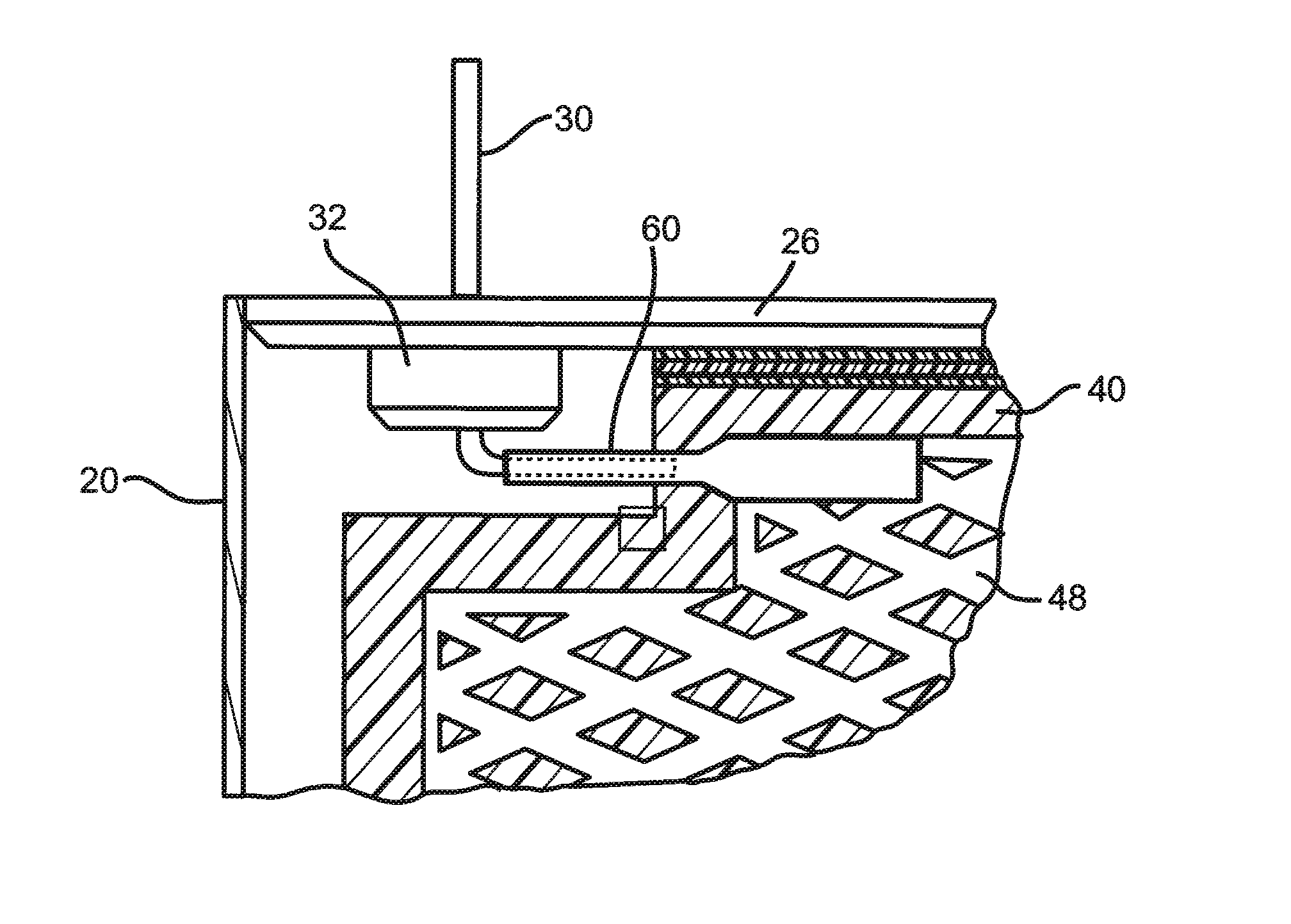
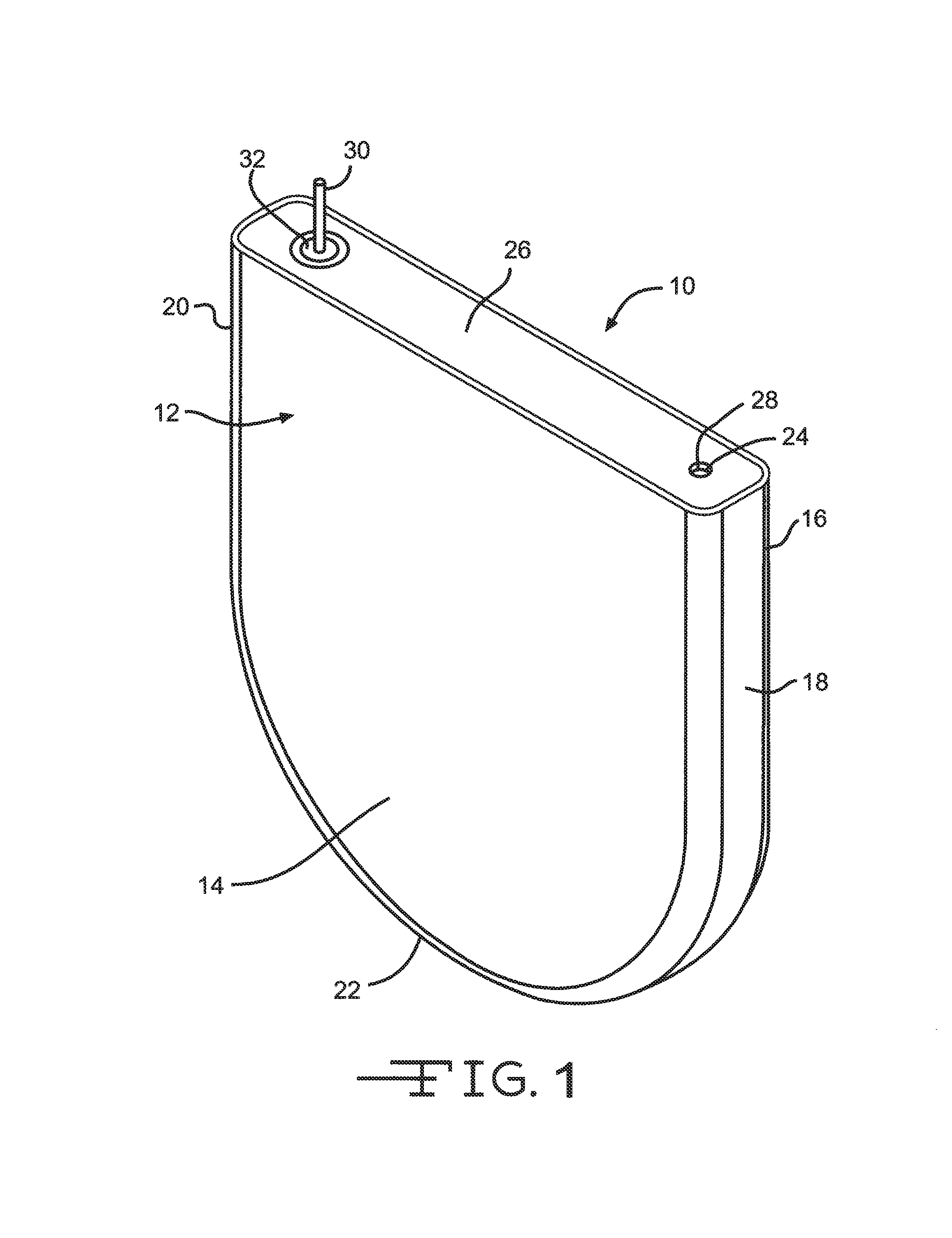
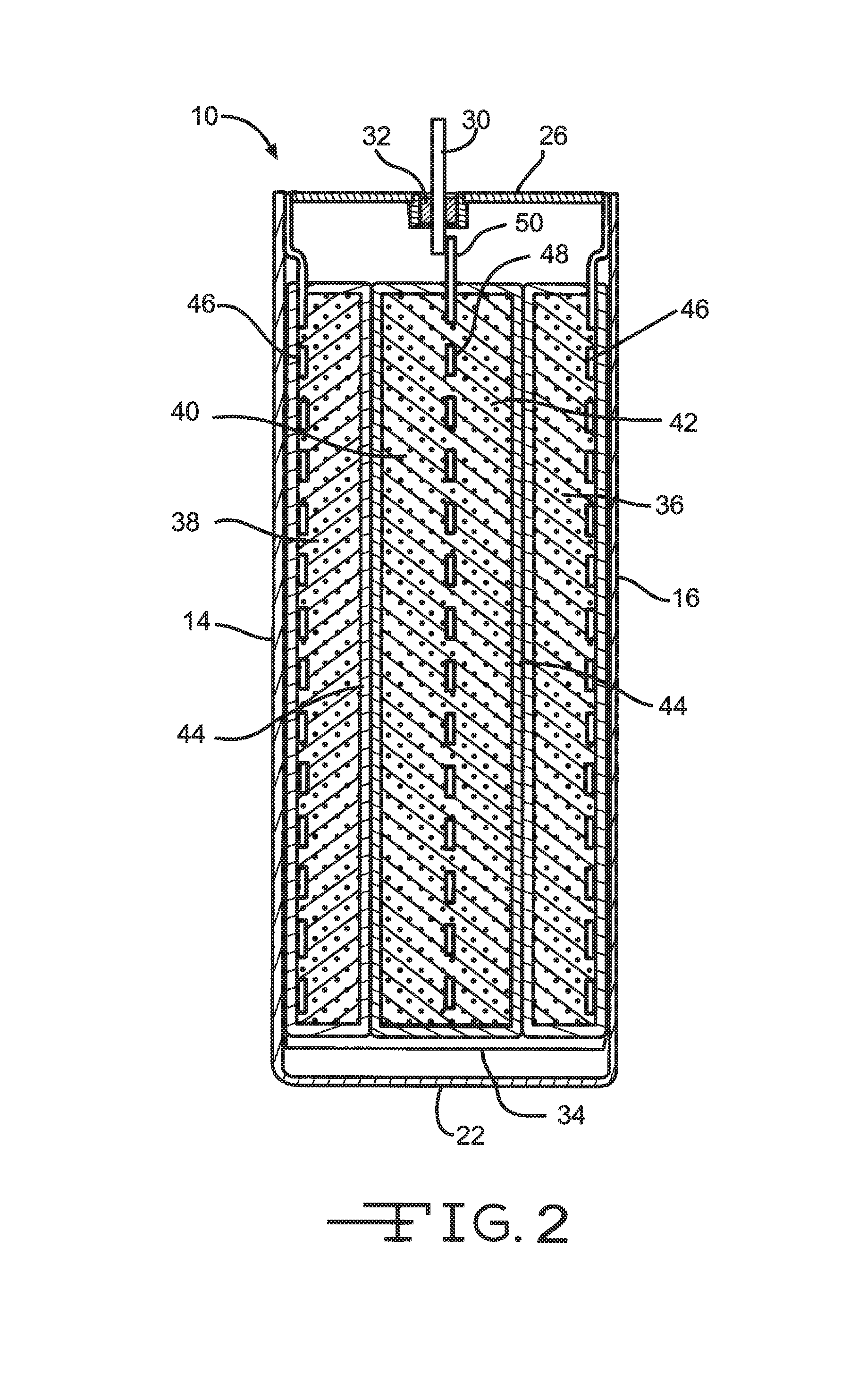
[0042]Referring now to FIGS. 1 and 2, there is shown an electrochemical cell 10 comprising a casing 12 having spaced-apart front and back walls 14 and 16 joined by curved end walls 18 and 20 and a curved bottom wall 22. The end walls can be curved to provide the casing having an oval cross-section, or they can be generally planar to provide a rectangular or prismatic cross-section. The casing has an opening 24 provided in a lid 26 used for filling the casing 12 with an electrolyte after the cell components have been assembled therein and lid 26 has been welded to casing 12. In its fully assembled condition shown in FIG. 1, a closure means 28 is hermetically sealed in opening 24 to close the cell. A terminal pin 30 is electrically insulated from lid 26 and casing 12 by a glass-to metal seal 32, as is well known to those skilled in the art.

[0043]Cell 10 comprises an electrode assembly 34 (FIG. 2) that further comprises anode electrode components 36, 38 and cathode electrode components...


PUM

PropertyMeasurementUnit
melting temperatureaaaaaaaaaa
frequency rateaaaaaaaaaa

Abstract

A magnetic pulse welding process for joining a current collector to a terminal pin in the construction of electrochemical cells is described. The magnetic pulse welding process utilizes a pulsed direct current and an electrically conductive coil to generate an electro-magnetic force that causes two work pieces to collide with each other and form a bond therebetween. Preferably, the method is used to bond the terminal pin to the cathode current collector. This method of attachment is suitable for either primary or secondary cells, particularly those powering implantable biomedical devices.

Description

CROSS-REFERENCE TO RELATED APPLICATION[0001]This application claims priority from U.S. Provisional Patent Application Ser. No. 61 / 614,652, filed Mar. 23, 2012.FIELD OF THE INVENTION[0002]The present invention relates to the art of electrochemical cells, and more particularly, to an improved method of connecting a current collector to a terminal pin. The present invention is of a magnetic pulse welding method by which the terminal pin is directly connected to the current collector.PRIOR ART[0003]The recent rapid development in small-sized electronic devices having various shape and size requirements requires comparably small-sized electrochemical cells of different designs that can be easily manufactured and used in these electronic devices. Preferably, the electrochemical cell has a high energy density, and one commonly used cell configuration is a prismatic, case-negative cell design having an intermediate cathode flanked by opposed anode components in contact with the casing and i...

Claims


Application Information

Patent Timeline
Patent Type & Authority Patents(United States)
IPC IPC(8): H01M2/20H01M2/22B23K20/06H01M2/06H01M50/176H01M50/528H01M50/534H01M50/538
CPCH01M2/22B23K20/06H01M2/06H01M4/661H01M2220/30B23K2103/18Y02E60/10H01M50/528H01M50/538H01M50/176H01M50/534
Inventor DAI, XIANGYANGFREITAG, GARY
Owner WILSON GREATBATCH LTD
Why Eureka
Try Eureka