Wave attenuation system and method

a wave attenuation and wave technology, applied in the field of breakwater systems, can solve problems such as redirection and dissipation of energy and momentum

Active Publication Date: 2017-01-31
BETCHER CHRISTOPHER FRED
View PDF29 Cites 9 Cited by
  • Summary
  • Abstract
  • Description
  • Claims
  • Application Information

AI Technical Summary

Benefits of technology

[0011]Impact, flow around, and fluid drag on all three tubes and their intermediate struts cause redirection and dissipation of energy and momentum by motion of the tubes in the surrounding water. The circular cross-section of the tubes and struts causes longitudinal, lateral, and vertical dissipation and redirection of water along the length of the breakwater. The rocking causes churning in both the transverse (vertical) and lateral (horizontal) directions. Each is orthogonal to the longitudinal direction of the tubes. Redirection longitudinally is primarily due to the strut geometry. In practice, tremendous dissipation of energy has been effected, providing adequate attenuation of wind-induced waves on enclosed bodies of water as well as near shorelines subject to sea waves.
[0012]In one embodiment of a method in accordance with the invention, the method may include attenuating waves in open water by providing an anchor, securing a tether to the anchor, providing an array of tubes fixed to one another and floating horizontally in water, and securing the array to the anchor by the tether. In providing the array, the array may constitute a triangulated cross-section having vertices defined by first and second tubes at least partially evacuated of water to render them buoyant. A third tube, the ballast tube, may be fixed with respect to the two floating tubes to move in substantially rigid body motion therewith.
[0014]A sleeve between the array and the tether is effective to reduce chafing or resist chafing between the tether and the array.
[0018]The apparatus rocks in the water. Rocking, by the array, in a subject body of water is in response to a wave impinging on the first tube as a lead tube, and passing under the second tube as a trailing tube, while the first and second tubes sweep the ballast tube through the water. The first and second tubes redirect water of the wave, transferring energy from the wave. The ballast tube transfers momentum and energy from the first and second tubes into water surrounding the ballast tube. The result is effective to substantially reduce the energy, momentum, and effective height of the wave impinging on the array.

Problems solved by technology

Impact, flow around, and fluid drag on all three tubes and their intermediate struts cause redirection and dissipation of energy and momentum by motion of the tubes in the surrounding water.

Method used


Image

  • Wave attenuation system and method
  • Wave attenuation system and method
  • Wave attenuation system and method

Examples


example i

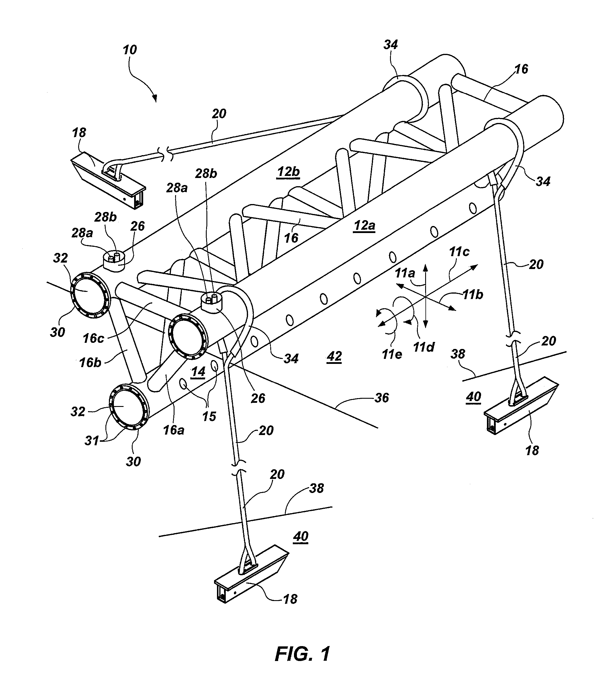
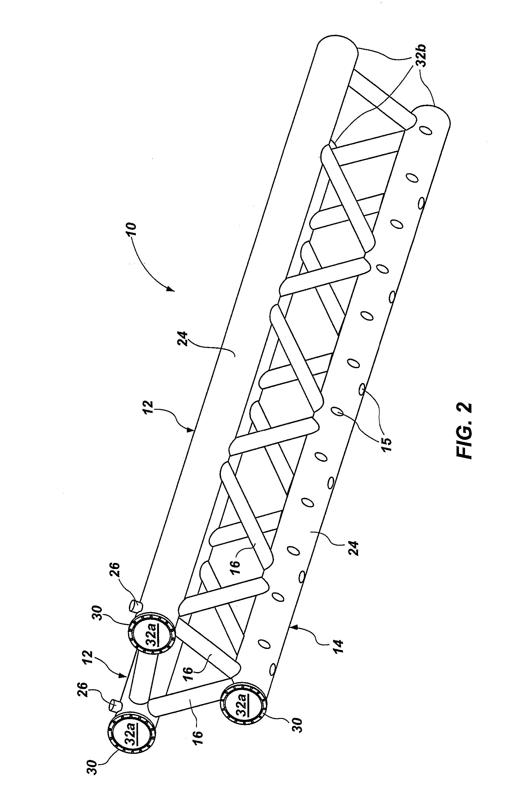
[0128]A wave attenuator 10 was constructed with a six foot surface width by eight foot depth. Making the wave attenuator to have a six foot width did not allow for effective diagonal bracing. Therefore, the surface braces were parallel to the wave coming in. The system worked very well.

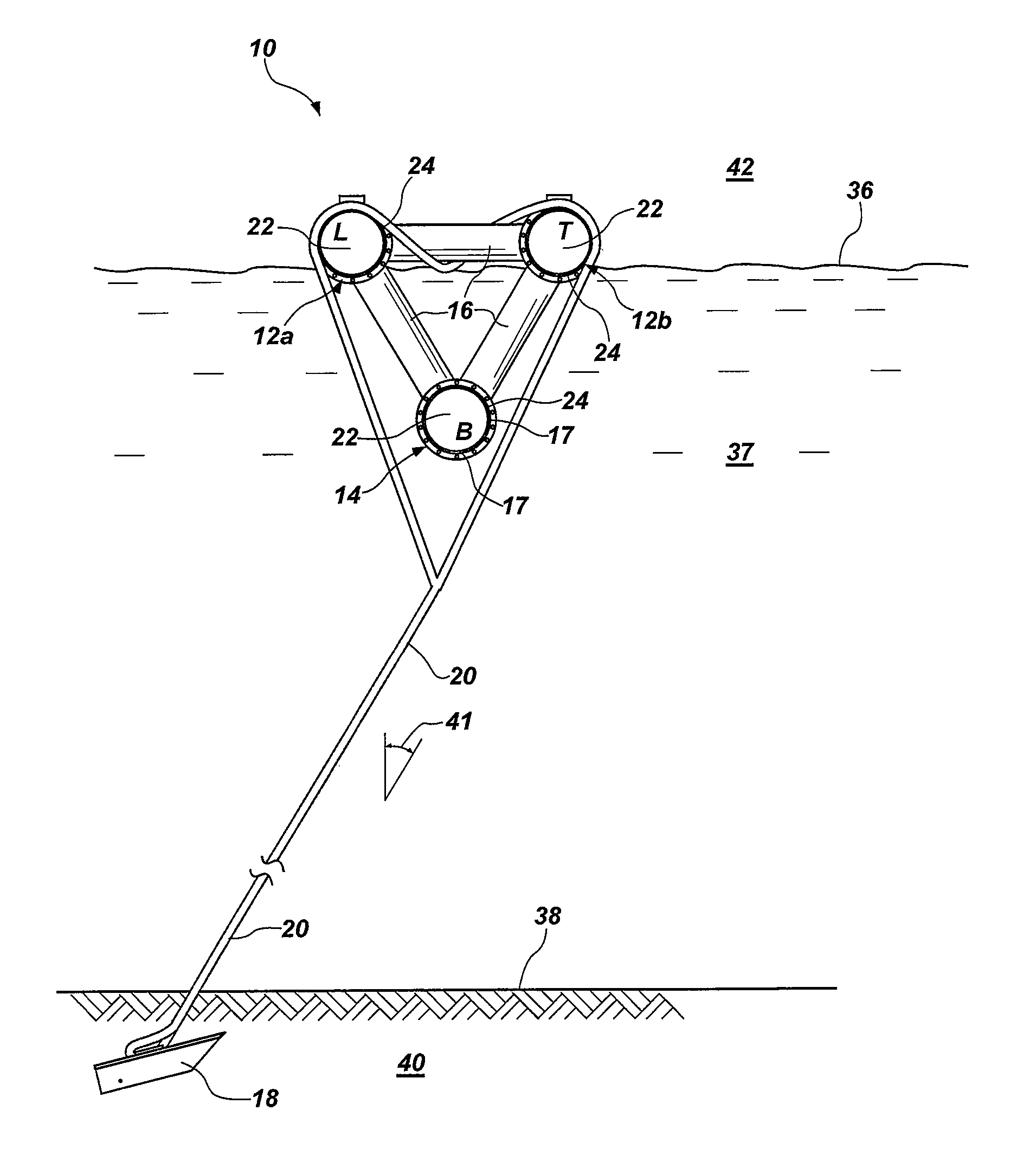
[0129]The ports 28 were added to add or remove (as required) water to the upper tubes 12. In the summer water was added to lower the attenuator 10 and make it more massive (added weight of water) and less visible. In the winter water was pumped out, raising the attenuator 10, making it more buoyant. Two one a half inch diameter pipes were welded into the 24 inch tube 12 (one pipe 29 was 23 inches, the other very short). Air blown into the short pipe (at five psi or less) forced water out through the long pipe 29. Flotation (buoyancy) can be infinitely adjusted.

example ii

[0130]A wave attenuator 10 (of 100 foot length) had an eight foot width across adjacent main float tubes 12 with diagonal, cross-bracing struts 16 worked well, an improvement over the six foot width with struts 16 running straight between.

example iii

[0131]Combining the wave attenuator 10 with a dock float system, was tested at a wave testing facility with scaled prototypes for testing. When hooked to pilings or other docks to reduce rocking the wave attenuator system 10 did not function satisfactorily. The attenuator 10 needs to move in response the wave 44.


PUM


Abstract

A breakwater (wave attenuation system) includes two horizontal tubes as buoyant members connected to one another, their cross-sections representing vertices of a triangle, whose legs are interconnecting struts. A perforated, submerged, ballast tube forms the third vertex. Wave motion is perpendicular to the length of the float tubes tethered to an anchor at the sea floor. A lead float tube rises in response to an approaching wave, often cutting off the wave crest, while a trailing float tube rises less and later as the wave passes. Asynchronous rising and falling of the leading and trailing, floating, top tubes rocks the breakwater, redirecting and dissipating wave momentum, energy, and water volume by rotating the assembly, thrashing the water.

Description

RELATED APPLICATIONS[0001]This application claims the benefit of co-pending U.S. Provisional Patent Application Ser. No. 62 / 000,370, filed May 19, 2014 for WAVE ATTENUATION SYSTEM AND METHOD and co-pending U.S. Provisional Patent application Ser. No. 62 / 118,173, filed Feb. 19, 2015 for WAVE ATTENUATION SYSTEM AND METHOD, both of which are incorporated herein by reference in their entirety. This application also incorporates by reference U.S. patent application Ser. No. 14 / 267,612, filed May 1, 2014 for CORROSION-AND-CHAFING-RESISTANT, MOORING SYSTEM AND METHOD, in its entirety.BACKGROUND[0002]Field of the Invention[0003]This invention relates to marine facilities, and more particularly to breakwater systems.[0004]Background Art[0005]The cyclic forces and motion of wave activity near shorelines has traditionally created problems such as erosion of shorelines, damage of shore-based equipment, navigation problems for small watercraft near reefs, shorelines, and shore-based equipment, a...

Claims


Application Information

Patent Timeline
Patent Type & Authority Patents(United States)
IPC IPC(8): E02B3/06
CPCE02B3/062Y02A10/11
Inventor BETCHER, CHRISTOPHER FRED
Owner BETCHER CHRISTOPHER FRED
Why Eureka
Try Eureka